Drive reduction theory hull
Drive-Reduction Theory
A theory of motivation developed by Clark L. Hull, the Drive-Reduction Theory focuses on how motivation originates from biological needs or drives. In this theory, Hull proposed a person’s behaviour is an external display of his desire to satisfy his physical deficiencies.
Discover 22 more articles on this topic
Don't miss these related articles:
- Motivation and Emotion
- Schachter-Singer Theory of Emotion
- Instinct Theory Of Motivation
- Cannon-Bard Theory of Emotion
- James-Lange Theory of Emotion
Origin of the Theory
Clark L. Hull was working at Yale University when he began to develop the drive-reduction theory. Inspired by several prominent scientists such as John B. Watson, Ivan Pavlov, Edward Thorndike and Charles Darwin, Hull based his theory on the earlier theories that relate to the concepts of motivation. His theory is grounded on the principle of homeostasis, believing that behaviour is one of the ways in which a person can maintain the state of homeostasis or balance.
The theory was further developed by Kenneth Spence as it began to be a major theory of motivation in the late 1940s.
The Theory
A “drive” is a state of arousal or tension triggered by a person’s physiological or biological needs. These needs include hunger, thirst, need for warmth, etc. In this theory, Hull stated that drives give rise to an individual’s motivation. Furthermore, Hull explained that an individual is in a state of need when his survival is threatened. When a person’s drive emerges, he will be in an unpleasant state of tension and the person will behave in such a way that this tension is reduced. To reduce the tension, he will begin seeking out ways to satisfy his biological needs. For instance, you will look for water to drink if you are thirsty. You will seek for food if you are hungry.
According to the theory, any behaviour that reduces the drives will be repeated by humans and animals. This is because the reduction of the drive serves as a positive reinforcement (i. e. a reward) for the behaviour that caused such drive reduction.
Application
Today, the drive-reduction theory is largely ignored in the field of psychology, despite the glory it has enjoyed from 1940s to 1950s. While drive-reduction theory is not much put into practical application nowadays, it is useful for students to learn about the theory, its concepts and its influence to modern psychology. In this way, the students would be able to know how other theorists built on the drive-reduction theory and why some theorists proposed concepts opposing Hull’s Theory.
Criticisms
While Hull’s drive-reduction theory explains how primary reinforcers are effective in reducing drives, many psychologists argued that the theory is not applicable in the concept of secondary reinforces. For example, money is a powerful secondary reinforcer as it can be used to purchase primary reinforcers like food and water. However, money in itself cannot reduce an individual’s drives. Another problem with the theory is that it does not provide an explanation about the reason behind people engaging in behaviors that are not meant to reduce drives, such as a person eating even if he is not hungry.
Full reference:
You Are Allowed To Copy The Text
The text in this article is licensed under the Creative Commons-License Attribution 4.0 International (CC BY 4.0).
This means you're free to copy, share and adapt any parts (or all) of the text in the article, as long as you give appropriate credit and provide a link/reference to this page.
That is it. You don't need our permission to copy the article; just include a link/reference back to this page. You can use it freely (with some kind of link), and we're also okay with people reprinting in publications like books, blogs, newsletters, course-material, papers, wikipedia and presentations (with clear attribution).
Related articles
Related pages:
instructionaldesign.org
Want to stay up to date? Follow us!
Follow @ExplorableMind
Drive Reduction Theory (C. Hull)
Hull developed a version of behaviorism in which the stimulus (S) affects the organism (O) and the resulting response (R) depends upon characteristics of both O and S.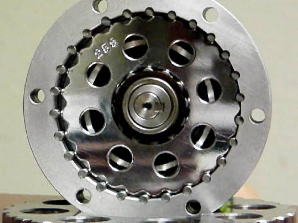 In other words, Hull was interested in studying intervening variables that affected behavior such as initial drive, incentives, inhibitors, and prior training (habit strength). Like other forms of behavior theory, reinforcement is the primary factor that determines learning. However, in Hull’s theory, drive reduction or need satisfaction plays a much more important role in behavior than in other frameworks (i.e., connectionism, operant conditioning).
Hull’s theoretical framework consisted of many postulates stated in mathematical form; They include: (1) organisms possess a hierarchy of needs which are aroused under conditions of stimulation and drive, (2) habit strength increases with activities that are associated with primary or secondary reinforcement, (3) habit strength aroused by a stimulus other than the one originally conditioned depends upon the closeness of the second stimulus in terms of discrimination thresholds, (4) stimuli associated with the cessation of a response become conditioned inhibitors, (5) the more the effective reaction potential exceeds the reaction theshold, the shorter the latency of response. As these postulates indicate, Hull proposed many types of variables that accounted for generalization, motivation, and variability (oscillation) in learning.
One of the most important concepts in Hull’s theory was the habit strength hierarchy: for a given stimulus, an organism can respond in a number of ways. The likelihood of a specific response has a probability which can be changed by reward and is affected by various other variables (e.g. inhibition). In some respects, habit strength hierarchies resemble components of cognitive theories such as schema and production systems .
ApplicationHull’s theory is meant to be a general theory of learning. Most of the research underlying the theory was done with animals, except for Hull et al. (1940) which focused on verbal learning. Miller & Dollard (1941) represents an attempt to apply the theory to a broader range of learning phenomena. As an interesting aside, Hull began his career researching hypnosis – an area that landed him in some controversy at Yale (Hull, 1933).
Here is an example described by Miller & Dollard (1941): A six year old girl who is hungry and wants candy is told that there is candy hidden under one of the books in a bookcase. The girl begins to pull out books in a random manner until she finally finds the correct book (210 seconds). She is sent out of the room and a new piece of candy is hidden under the same book. In her next search, she is much more directed and finds the candy in 86 seconds. By the ninth repetition of this experiment, the girl finds the candy immediately (2 seconds). The girl exhibited a drive for the candy and looking under books represented her responses to reduce this drive. When she eventually found the correct book, this particular response was rewarded, forming a habit. On subsequent trials, the strength of this habit was increased until it became a single stimulus-response connection in this setting.
Principles- Drive is essential in order for responses to occur (i.
 e., the student must want to learn).
 - Stimuli and responses must be detected by the organism in order for conditioning to occur ( i.e., the student must be attentive).
- Response must be made in order for conditioning to occur (i.e., the student must be active).
- Conditioning only occurs if the reinforcement satisfied a need (i.e, the learning must satisfy the learner’s wants).
- Hull, C. (1933). Hypnosis and Suggestability: An Experimental Approach. New York: Appleton-Century-Crofts.
- Hull, C. (1943). Principles of Behavior. New York: Appleton-Century-Crofts.
- Hull, C. et al. (1940). Mathematico-Deductive Theory of Rote Learning. New Haven, NJ: Yale University Press.
- Miller, N. & Dollard, J. (1941). Social Learning and Imitation. New Haven, NJ: Yale University Press.
For more about Hull and his work, see: http://en. wikipedia.org/wiki/Clark_L._Hull
Synthesis of the lever mechanism of the ground drive of a rod well pumping unit and substantiation of its new kinematic scheme
SUMMARY for oil production, it is proposed to use a class III six-link mechanism instead. For this, the authors carried out a structural-kinematic synthesis of this mechanism, and on this basis, the possibility of its use as a ground drive of the SHSNU was substantiated, a new technical solution was proposed for this. The new technical solution includes a number of devices, mechanisms and assemblies, which, unlike the basic pumping unit used in real oil fields, can significantly reduce the dynamic load on the drive. In addition, by reducing the size and reducing the metal consumption, they make it possible to balance the pump drive mechanism with minimal energy and cost.
The presence in the structure of the proposed SC drive mechanism of a movable rigid circuit, which, in combination with three drivers, has wide kinematic and dynamic capabilities, allows this design to simultaneously perform the functions of a balancing device and at the same time a rectilinear-guiding mechanism. Thus, the method of synthesizing the lever drive mechanism and new schemes proposed by the authors, when introduced into production, can achieve a significant economic effect.
ABSTRACT
On the basis of the analysis of merits and demerits of the lever four-unit mechanism II of a class of the drive of the sucker-rod borehole deep and pump installation applied in crafts to oil production it is offered to use to the place him the six-unit mechanism III of a class. For this purpose, the authors have carried out structural and kinematic synthesis of this mechanism, and on this basis the possibility of its application as the land drive of pump installation is proven, the new technical solution for implementation of it is proposed. The new technical solution turns on a number of devices, mechanisms and knots which, unlike the basic mechanism of the pumping unit used in real oil fields allow to lower dynamic loads of the drive considerably. Besides, due to reduction of dimensions and decrease in metal consumption they give the chance to counterbalance the pump drive mechanism at the minimum expenses of energy and means. Existence in structure of the offered mechanism of the SK drive of the mobile rigid contour possessing in combination with three leads ample kinematic and dynamic opportunities allows to carry out this design at the same time functions of the counterbalancing device and in too time is rectilinear - the directing mechanism. Thus, the new schemes offered by authors a technique of synthesis of the lever mechanism of the drive and offered at introduction in production allow to reach considerable economic effect.
In oilfields with mechanized oil extraction, one of the main types of equipment is still a rod well pumping unit (SHSNU), where a pumping unit (SK) is used as a ground drive, which is a four-link mechanism of the second class, containing a crank pair and a two-arm rocker (balancer) pivotally connected to it, having an arc head on the front arm, equipped with a flexible element connecting the balancer with the suspension point of the rod column [6]. During the operation of the four-link mechanism SK (Fig. 1), the rotational movement of the crank 1 by means of the connecting rod 2 is converted into a reciprocating movement of point Р rod suspension (TPSh).
The disadvantages of the mechanism include metal consumption, large dimensions and, as a result, a large mass, which is aggravated by the use of heavy cargo counterweights.
This SC mechanism is also unreliable in operation due to frequent failures of the gland rod and its other moving parts.
Also known is a six-link mechanism of the second class of the SC drive, obtained by attaching elements of a two-wire group to the main four-link crank-rocker mechanism at the hinge point of the connection of the head of the balancer and the rack in such a way that the two-wire group in combination with the front arm of the balancer constitutes an approximately rectilinear guide mechanism [1].
However, in this SC drive mechanism, despite the use of a special balancer head in the form of a hinged-lever rectilinearly guiding mechanism, the required law of movement of the rod suspension point is not provided, moreover, the use of cargo counterweights is not excluded, which inevitably leads to large dimensions and the masses.
In a four-link mechanism of the second class of the SK drive (Fig. 2, and ), containing a balancer 1 with an arc head with front and rear shoulders, the last of which has a gear rack mechanism at the point of articulation with the connecting rod 2, the gear wheel 3 of which made with the possibility of movement between the fixed and movable rails 4 and 5, installed on the balancer by means of tension springs 15 of the shock absorber 6 [2].
Figure 2. Structural and kinematic diagrams of the SC drive mechanisms:
a) SC balancer; b) general view of the SC drive transmission; c) chain transmission of variable gear ratio with rocker-spring closed power circuit
In this technical solution, the authors attempted to transform the basic mechanism shown in fig. 1 by changing the arm of the balancer during its operation. This is done by changing the length BC rear arm BC balancer 3 by the value BC using a rack and pinion pair with a spring shock absorber. During the operation of the mechanism, the length BC of the arm BC of the balance bar changes according to the change in the load on the drive, i.e. with increasing load, the length of the rear arm increases, and with a decrease in load, it decreases. However, the implementation of the middle pair of the two-wire group of the four-link mechanism in the form of a rack and pinion mechanism with spring shock absorbers somewhat complicates the design of the balancer, although here the impact dynamic load on the drive is compensated quite effectively.
The same technical effect is obtained in the SC transmission mechanism (Fig. 2, b ), containing a two-stage closed-type gearbox 1 with a spur gear 2 of the first stage and a chain transmission 3 of the second stage [4]. The first stage is kinematically connected to the electric motor 5 by means of a V-belt transmission 4. The chain transmission has a round drive sprocket 6, an elliptical driven sprocket 9 and a toothed chain 7. An elliptical sprocket mounted on the output shaft 8 inside the gearbox housing, in addition to its main purpose , combines the function of a balancing device (counterweight). A crank 10 of the SK mechanism is rigidly mounted at the end of the output shaft outside the gearbox. The chain drive has a tensioner with reciprocating-rotary strokes (Fig. 2, to ). Moreover, in the tensioner, which forms a closed rocker-spring circuit, as the elliptical sprocket 9 rotates, the tension in the chain 7 smoothly changes. 11 of the drive sprocket together with the rocker arms 12 and 13 associated with them.
Analyzing the above information, we can conclude that by combining the advantages of each of the above mechanisms in one conventional SC drive mechanism, it is possible to achieve a better balancing of the load on the drive. However, this, in turn, somewhat complicates the design of the SC mechanism, making it metal-intensive and bulky. Moreover, with this approach, the question of the implementation of any required law of motion of the TPS is not completely resolved.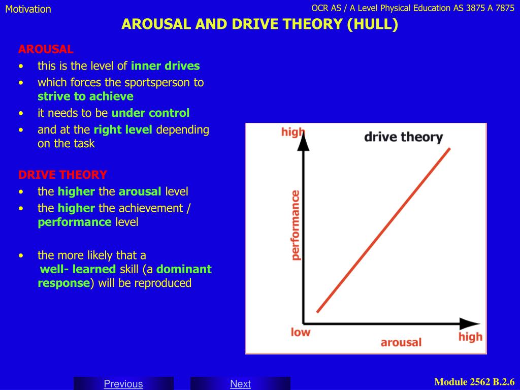 Obviously, this can be achieved by selecting such a scheme of the SC mechanism that would provide a change in the arms of the balancer during the operation of the mechanism due to the constructive ratios of its links. One of the effective methods for achieving this goal can be a structural-kinematic synthesis of the mechanism based on the scheme of the existing basic model [5].
For an effective constructive solution of this problem and in order to reduce shock dynamic loads on the SC drive, a structural-kinematic synthesis was carried out, which subsequently allowed us to propose a new technical solution.
Length variability arm VS of the SK balancer of the mechanism shown in fig. 1, can be provided by using a class III articulated lever six-link mechanism instead of a articulated four-link mechanism, which increases the reliability of the SC in comparison with its counterpart with a rack and pinion pair. For this shoulder BC of the balance beam will be replaced by a dyad VDC , which ensures the variability of the distance between the centers of the hinges C and B (not shown in the figure). The resulting articulated six-link OABDC has two degrees of freedom. To eliminate this extra degree of freedom, we connect the link ВD of this articulated six-link using the binary link EF with two rotational kinematic pairs, imposing one connection condition. As a result, we obtain a block diagram of a single-moving six-link mechanism of class III (Fig. 3).
Consider the algorithms for the synthesis of a new class III SC mechanism. To do this, with links 1–4 of this mechanism, we rigidly connect the moving coordinate systems , respectively. The geometric parameters of the links of the class III mechanism under consideration should provide the necessary rocking movement of the balancer according to equation , excluding shock dynamic loads.
The synthesized mechanism is a class III transmission mechanism and consists of an executive kinematic chain - two moving coordinates and , performing rotational movements according to the equation , and the closing kinematic chain - dyads ABD with an attached binary link EF with rotational kinematic pairs.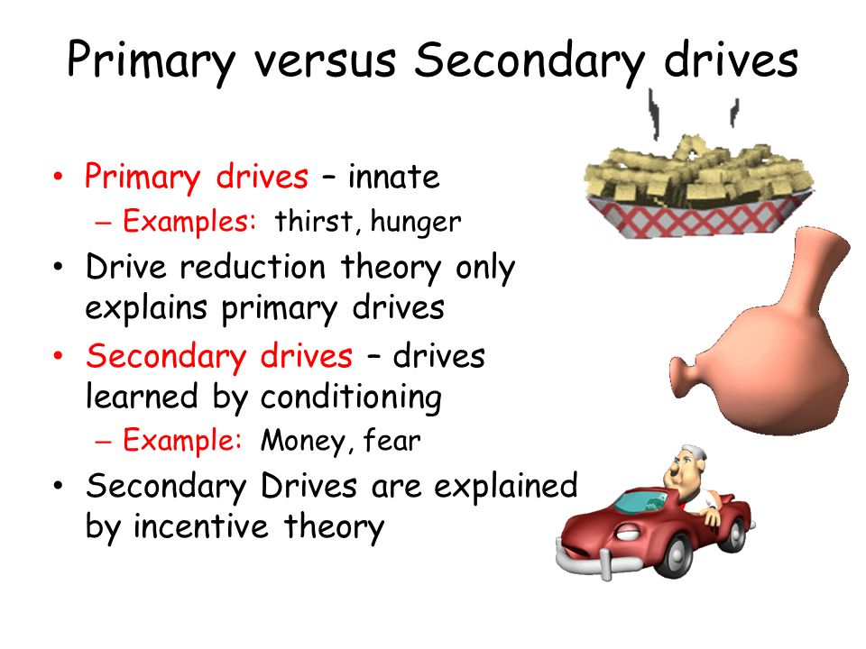
Figure 3. Calculation scheme for structural-kinematic synthesis
class III six-link mechanism
The vector of the synthesis parameters of the studied mechanism is subdivided into:
- vectors variable
- and approximated synthesis parameters
Where: - hinges A and D in coordinate systems and and link length AB BD diades ABD ; - coordinates of hinges E and F in coordinate systems and OXY , respectively, and the length of the binary link EF .
Vector of variable synthesis parameters is set using LP - sequence. In this case, the condition
must be satisfied. (1)
(1)
, (2)
where
. (3)
Hinge coordinates « В» in the absolute coordinate system OXY and the angle in equation (3) are determined by solving the problem of the positions of the dyad ABD .
After the expression substitution (3) in the equation (2) and the unpertured replacement of variables
, , (4)
Function (2) is represented in the form of linear forms of synthesis parameters , vol. e.
( k =1.2), (5)
Representation of function (2) in the form of linear forms (5) allows us to formulate and solve approximation problems for the synthesis of a binary link EF, based on Chebyshev and quadratic approximations and gradient methods [7].
The proposed synthesis technique allowed us to substantiate the prospects and the possibility of effective use of a class III six-link mechanism as ground-based SHSN drives.
We have proposed a SC drive mechanism containing a crank 1, a connecting rod 2 pivotally connected to it, which is one of the leashes of the three-drive group with a rigid triangular closed loop 4 (hereinafter referred to as the contour), the remaining leashes 5 and 7 of which are pivotally connected to the rack 6 In this case, the leash 7 in conjunction with the circuit 4 is a variable rear arm of the two-arm balance bar 3, the other front arm 8 of which has an arc head 9, which communicates the reciprocating rectilinear movement of the suspension point of the SC rod column associated with it (Fig. 4). Thus, the mechanism formed by attaching a three-drive group to a crank pair is a class III six-link mechanism with one degree of mobility [3].
Figure 4. Scheme of a class III six-link mechanism,
used as a ground drive SHSNU
The ratio of the lengths of the sides of the triangular contour 4 and other links on the basis of structural-kinematic synthesis must be selected so that during one cycle of the operation of the SC drive mechanism, the length of the rear arm of the balancer, depending on the relative position of the component links 4 and 7, changes, thereby providing the required arm resistance is directly proportional to the drive load.
During the operation of the proposed mechanism, the rotation of the crank 1 by means of the connecting rod 2, which is one of the drivers of the three-driver group with a rigid contour 4, and its second driver 5 is converted into a reciprocating rocking movement of the balancer 3, which, through the arc head 9, mounted on the front arm 8 balancer, goes into a rectilinear reciprocating motion of the TPSh. At the same time, with an increase in the load on the drive, the variable arm of the balancer increases, and with a decrease in the load, it decreases.
The presence in the structure of the SC drive mechanism of a movable rigid circuit, which, in combination with three leashes, has wide kinematic and dynamic capabilities, allows this design to simultaneously perform the functions of a balancing device and at the same time a rectilinear-guiding mechanism. Thus, the proposed technical solution makes it possible to reduce the metal consumption and dimensions of the SC drive mechanism.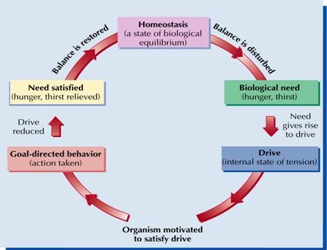 The proposed method of structural-kinematic synthesis makes it possible to determine the optimal ratios not only of the SC drive mechanisms, but also of other similar planar mechanisms of complex structures containing two-drive groups in the structure.
References:
1. Aliverdizade K.S. Rod pump drives. - M.: Nedra, 1973.
2. Baigunchekov Zh.Zh., Akhmetov S.M., Serikov N.Zh. and others. The balancer of the machine - rocking chairs. - Description of the invention according to the Provisional patent of the Republic of Kazakhstan No. 4049, class. F04B 47/02, 1996. - Bull. No. 4.
3. Djoldasbekov U.A., Baygunchekov Zh.Zh., Akhmetov S.M. etc. The drive mechanism of the rocking machine. - Description of the invention according to the Provisional patent of the Republic of Kazakhstan No. 8845, class. F04B 47/02, 2000. - Bull. No. 4.
4. Kushekov A.U., Akhmetov S.M. Transmission of the pumping unit: Description of the invention according to the decision to issue a provisional patent according to application No. 970665.1 dated 14.07097, class. F 04 B 47/02.
5. Levitsky N.I. Theory of mechanisms and machines. Textbook for universities. - 2nd ed., revised. and additional - M.: Nauka, 1990.
6. Molchanov G.V., Molchanov A.G. Machinery and equipment for oil and gas production. – M.: Nedra, 1984.
7. Zhumadil Zh. Baiguchekov, Raj Gill, Anthony S. White, Nurlan Zh. Baiguchekov. The Basis of Structural and Parametric Synthesis of The Parallel Manipulators with Functionally Independent Drives (Part I & Part II) // Proc. of the Intern. Conf. on Gearing, Transmissions, and Mechanical Systems (3–6 July 2000, Nottingham Trent University, UK). - R. 1–19.
References:
1. Aliverdizade K.S. Rod pump drives. Moscow, Nedra Publ., 1973. (In Russian).
2. Bajgunchekov Zh.Zh., Ahmetov S.M., Serikov N.Zh. The balance of the machine – rocking. Description of the RK invention for a provisional patent number 4049, cl. F04B 47/02, 1996 Bul. no. 4. (In Russian).
3. Dzholdasbekov U.A., Bajgunchekov Zh.Zh., Ahmetov S.M. The mechanism of the drive pumping unit. Description of the RK invention for a provisional patent number 8845, cl. F04B 47/02, 2000 Bul. no. 4. (In Russian).
4. Kushekov A.U., Ahmetov S.M. Transmission pumping unit: Description of the invention by the decision to grant a preliminary patent on the application No. 970665.1 of 14.07097, cl. F 04 B 47/02. (In Russian).
5. Levitskij N.I. Theory of mechanisms and machines. Textbook for high schools. 2 ed. Moscow, Nauka Publ., 1990. (In Russian).
6. Molchanov G.V., Molchanov A.G. Machinery and equipment for oil and gas. Moscow, Nedra Publ., 1984. (In Russian).
7. Zhumadil Zh. Baiguchekov, Raj Gill, Anthony S. White, Nurlan Zh. Baiguchekov. The Basis of Structural and Parametric Synthesis of The Parallel Manipulators with Functionally Independent Drives (Part I & Part II). Proc. of the Intern. Conf. on Gearing, Transmissions, and Mechanical Systems (3–6 July 2000, Nottingham Trent University, UK). R. 1–19.
Finding ways to reduce vibration levels in industrial sewing machines
References:
Uzakova, L.P., Fayziev S.Kh., Mukhammedova M.O. Exploration of possibilities to reduce vibration levels in industrial sewing machines. - Text: direct // Young scientist. - 2014. - No. 19 (78). — S. 252-254. — URL: https://moluch.ru/archive/78/13223/ (date of access: 12/13/2022).
Vibration of machines can lead to disorganization of mechanisms, premature wear and destruction of parts, to a decrease in the reliability of machines and, in some cases, to disruption of the technological process.
The problem of combating noise and vibration in light industry is complicated by the presence of a large number of working machines in the workshops, it includes a whole range of measures.
By improving the design of the actuator drive of sewing machines to improve the working conditions of operators in the garment industry, it is to find ways to reduce the vibration and noise levels of industrial sewing machines.
To solve this problem, it will be necessary to solve the following tasks:
- mathematical modeling of the kinematics of the sewing machine actuators with possible drive options for the vertical movement of the racks;
- determination of the functions of the kinematic disturbance of the drive circuits;
- development of a dynamic model of the material movement mechanism; determination of its parameters and mathematical modeling of natural and forced oscillations of the mechanism;
- development and substantiation of a dynamic model of the drive of the sewing machine actuators;
- mathematical modeling of natural and forced vibrations in the actuator drive;
When solving the above problems, methods of the theory of mechanisms and machines and the theory of differential equations in ordinary and partial derivatives are used.
The developed software for solving the problems of vibroacoustic analysis of the mechanisms of sewing machines in the aggregate constitutes a methodological and scientific basis for designing and upgrading the drive of the actuators of industrial sewing machines.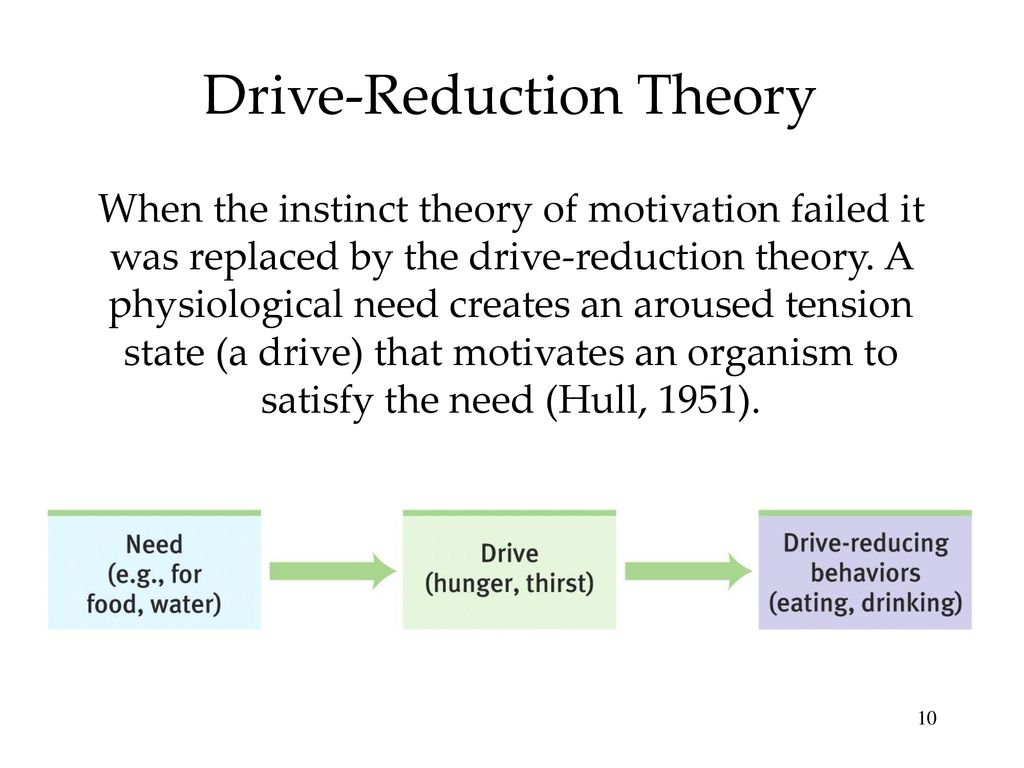
Most of the studies devoted to the problems of noise and vibration of machines contain sections reflecting the methods and means of their reduction. Vibration isolation is achieved by reducing the transmission coefficient of acoustic energy with the introduction of elastic vibration isolating pads, acoustic bridges on the paths of structural noise propagation from the sewing machine body to the desktop.
At present, various vibration-isolating materials are widely used in sewing machines: sponge rubber, sponge rubber, foam plastic, foam rubber, hair felt, cardboard, etc.
The proposed mathematical model of the sewing machine vibration isolation system makes it possible to determine its vibration isolation effect in decibels and dynamic characteristics using the initial parameters method in matrix form. It is proposed to install the machine heads on vibration isolators made of VP rubber (TU 38–105376–72) grades 4926 and to fix the electric motor with rubber bushings 4947. machines in the frequency range of 8–1000 Hz to values below the standard.
A shock absorber is also available to fit under the legs of the sewing machine table. The shock absorber includes a rectangular body measuring 1.25x0.6 m. This size ensures that all four legs are installed on one shock absorber. Porous foam material with a density of 40 kg/m must be placed in the casing. A 2.5 cm thick sheet of pressed wood is placed on top of the foam.
Vibration dampening is the application of special materials to vibrating metal surfaces with high internal loss of vibrational energy. As a result, its loss coefficient increases, resonant oscillations of the structure are suppressed, and the transmission of sound energy from the place of excitation to the place of radiation decreases.
If used in conjunction with a sewing machine, a set of covers made of multilayer materials, the physical and chemical characteristics of which provide protective properties - allow isolating the operator from harmful noise effects.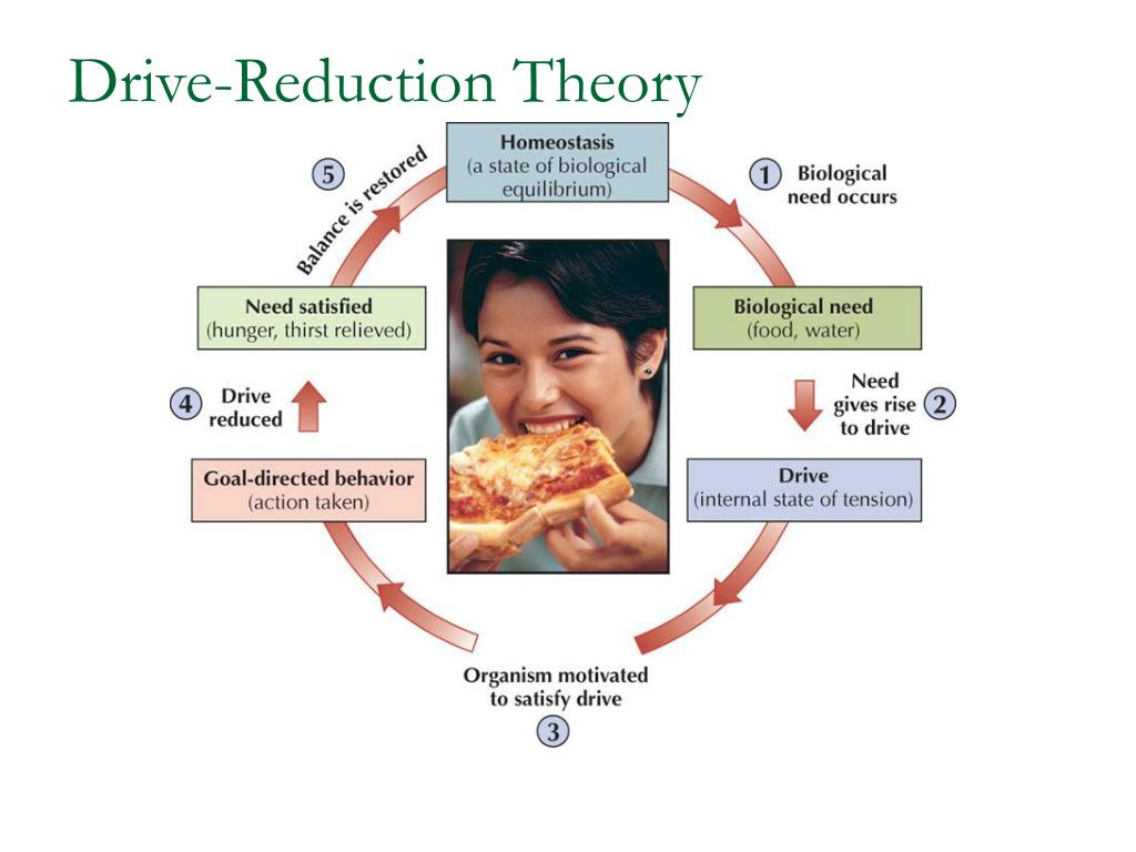 The covers have different configurations and are attached using hinged loops to the surface of the machine's desktop. The proposed kit contains, for example, a cover that covers the movement area of the sewing machine needle. This lid has a cutout bottom to allow for machine maintenance and a top filled with sound-absorbing cushioning material. The covers are provided with cavities designed to effectively dissipate the heat generated during the operation of the sewing machine.
An important condition for obtaining a quality stitch on a sewing machine with a rack mechanism for transporting fabric is the constancy and reliability of the contact of the rack with the fabric during transportation.
Based on the requirements of a technological nature, the required trajectory of the rail movement consists of the following sections:
- - The feeder rises vertically above the level of the needle plate and clamps the materials between the teeth and the lower plane of the presser foot.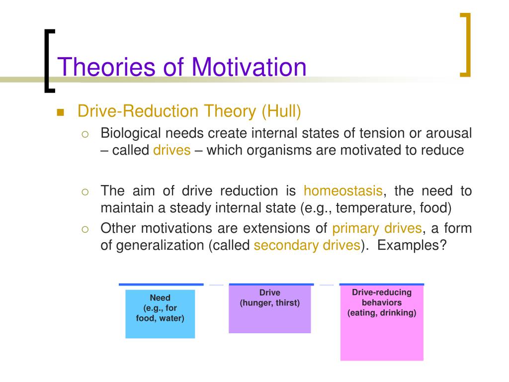 This section corresponds to the movement of the fixed materials by the rail by a given value. The rail moves parallel to the needle plate surface in the desired direction of material movement. The rail goes down vertically. In the idling section, there are two options for the movement of the rail: 1) the rail moves along a trajectory that is a mirror image of the trajectory; 2) the rail moves along an arbitrary trajectory.
Three-center cams are used in the drive of sewing machine mechanisms to ensure the movement of their working bodies with stops in extreme positions: the pusher moves according to the cyclogram "forward - stop - reverse - stop". The advantage of these cams is that they allow the pusher to be made in the form of a fork, eliminating the need to use counter cams for positive locking.
The task of designing such cams differs from the task of designing, for example, cams used in weaving machines (batan, shedding mechanisms): after determining the relationship between the radii of curvature of the sections of the profile, it becomes necessary to calculate the kinematic functions of the pusher according to the geometric parameters of the cam.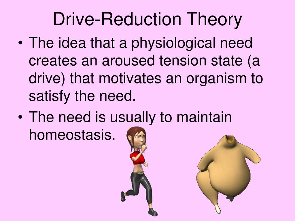
The dependencies obtained show that the movement of the pusher is carried out with a soft impact, that is, the mechanism in a certain region of the cam rotation frequencies can be a source of increased vibration and noise emitted by the machine by which it is used. The jump in the analogue of the angular acceleration of the pusher is mainly determined by the ratio of the difference in the radii of curvature of the sections of the profile to the distance between the axes of rotation of the cam and the pusher.
As a result, a new mechanism for transporting fabric was synthesized in the dimensions of a similar mechanism for transporting fabric of a sewing machine, with specified technological and design parameters, with a rectilinear and almost parallel to the throat plate movement section of the middle tooth of the rack.
The largest amplitudes of velocities and, accordingly, the radiated noise have natural oscillations excited at a frequency of 1023 Hz. The fluctuations at the frequencies of 2632 Hz, 2024 Hz and 959 Hz are also significant.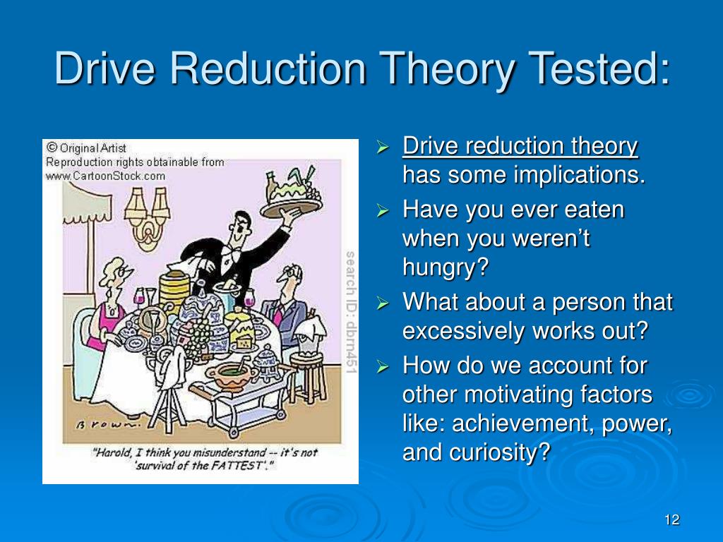 At given frequencies, the amplitudes of accompanying oscillations are higher than the amplitudes of oscillations excited by the initial perturbation. At a frequency of 1023 Hz, the nth span of a leaf spring has the highest velocity amplitude, at frequencies of 2632 Hz and 2024 Hz - the 1st span, at a frequency of 959 Hz - a toothed rack.
The amplitudes of the speeds of oscillations excited by the initial disturbance do not depend on the speed of the main shaft of the machine, but depend on the force P0 of the initial pressure of the foot on the material being sewn. On the contrary, the amplitudes of the accompanying oscillations, respectively, depend on the frequency of the kinematic perturbation and do not depend on the force.
To determine the influence of specific parameters on the level of vibration velocities of the system, the moments of inertia of the masses, the stiffness coefficients of the shaft sections and belt drives, the number of revolutions of the main shaft and the pressure of the presser foot were varied.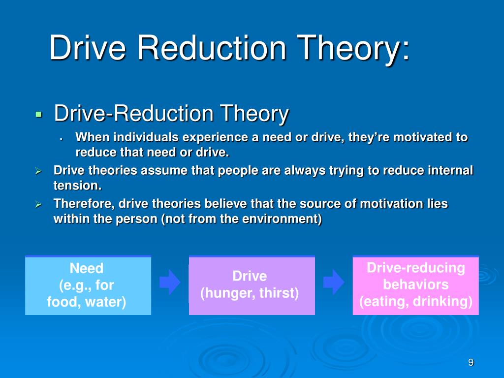
Amplitudes of vibration velocities of accompanying vibrations caused by the resistance force of the presser foot in octave bands of 500...2000 Hz are insignificant. In the same bands, all oscillations of the pulley that simulates the inertial properties of the rotor of the electric motor are insignificant.
The needle movement mechanism has the highest amplitudes of vibration velocities: accompanying vibrations caused by a variable reduced moment of inertia at the 3rd frequency; accompanying vibrations caused by the resistance of the presser foot - at the 1st frequency; natural oscillations caused by the initial disturbance - at the 2nd frequency.
An increase in the rotation frequency of the main shaft leads to a sharp increase in the amplitudes of vibration velocities caused by a change in the reduced moments of inertia of the masses of the links and initial conditions due to the periodicity of the process. With 1(k) decrease in the frequency of the perturbation, the amplitudes of the vibration velocities of the accompanying oscillations, caused by the resistance force of the presser foot, increase.