Types of distortions
Distortion - Types and Causes
This article covers several key issues on distortion in arc welded fabrications, especially basic types of and factors affecting the degree of distortion.
What causes distortion?
Because welding involves highly localised heating of joint edges to fuse the material, non-uniform stresses are set up in the component because of expansion and contraction of the heated material. Initially, compressive stresses are created in the surrounding cold parent metal when the weld pool is formed due to the thermal expansion of the hot metal (heat affected zone) adjacent to the weld pool. However, tensile stresses occur on cooling when the contraction of the weld metal and the immediate heat affected zone is resisted by the bulk of the cold parent metal.
Click here to see our latest technical engineering podcasts on YouTube.
The magnitude of thermal stresses induced into the material can be seen by the volume change in the weld area on solidification and subsequent cooling to room temperature. For example, when welding CMn steel, the molten weld metal volume will be reduced by approximately 3% on solidification and the volume of the solidified weld metal/heat affected zone (HAZ) will be reduced by a further 7% as its temperature falls from the melting point of steel to room temperature.
If the stresses generated from thermal expansion/contraction exceed the yield strength of the parent metal, localised plastic deformation of the metal occurs. Plastic deformation causes a permanent reduction in the component dimensions and distorts the structure.
What are the main types of distortion?
Distortion occurs in six main forms:
- Longitudinal shrinkage
- Transverse shrinkage
- Angular distortion
- Bowing and dishing
- Buckling
- Twisting
The principal features of the more common forms of distortion for butt and fillet welds are shown below:
Contraction of the weld area on cooling results in both transverse and longitudinal shrinkage.
Non-uniform contraction (through thickness) produces angular distortion in addition to longitudinal and transverse shrinkage.
For example, in a single V butt weld, the first weld run produces longitudinal and transverse shrinkage and rotation. The second run causes the plates to rotate using the first weld deposit as a fulcrum. Hence, balanced welding in a double side V butt joint can be used to produce uniform contraction and prevent angular distortion.
Similarly, in a single side fillet weld, non-uniform contraction produces angular distortion of the upstanding leg. Double side fillet welds can therefore be used to control distortion in the upstanding fillet but because the weld is only deposited on one side of the base plate, angular distortion will now be produced in the plate.
Longitudinal bowing in welded plates happens when the weld centre is not coincident with the neutral axis of the section so that longitudinal shrinkage in the welds bends the section into a curved shape. Clad plate tends to bow in two directions due to longitudinal and transverse shrinkage of the cladding; this produces a dished shape. Dishing is also produced in stiffened plating. Plates usually dish inwards between the stiffeners, because of angular distortion at the stiffener attachment welds (see main photograph).
In plating, long range compressive stresses can cause elastic buckling in thin plates, resulting in dishing, bowing or rippling.
Distortion due to elastic buckling is unstable: if you attempt to flatten a buckled plate, it will probably 'snap' through and dish out in the opposite direction.
Twisting in a box section is caused by shear deformation at the corner joints. This is caused by unequal longitudinal thermal expansion of the abutting edges. Increasing the number of tack welds to prevent shear deformation often reduces the amount of twisting.
How much shall I allow for weld shrinkage?
It is almost impossible to predict accurately the amount of shrinking. Nevertheless, a 'rule of thumb' has been composed based on the size of the weld deposit. When welding steel, the following allowances should be made to cover shrinkage at the assembly stage.
Transverse shrinkage
Fillet Welds 0.8mm per weld where the leg length does not exceed 3/4 plate thickness
Butt weld 1.5 to 3mm per weld for 60° V joint, depending on number of runs
Longitudinal shrinkage
Fillet Welds 0.8mm per 3m of weld
Butt Welds 3mm per 3m of weld
Increasing the leg length of fillet welds, in particular, increases shrinkage.
What are the factors affecting distortion?
If a metal is uniformly heated and cooled there would be almost no distortion. However, because the material is locally heated and restrained by the surrounding cold metal, stresses are generated higher than the material yield stress causing permanent distortion. The principal factors affecting the type and degree of distortion, are:
- Parent material properties
- Amount of restraint
- Joint design
- Part fit-up
- Welding procedure
Parent material properties
Parent material properties which influence distortion are coefficient of thermal expansion and specific heat per unit volume. As distortion is determined by expansion and contraction of the material, the coefficient of thermal expansion of the material plays a significant role in determining the stresses generated during welding and, hence, the degree of distortion. For example, as stainless steel has a higher coefficient of expansion than plain carbon steel, it is more likely to suffer from distortion.
Restraint
If a component is welded without any external restraint, it distorts to relieve the welding stresses. So, methods of restraint, such as 'strong-backs' in butt welds, can prevent movement and reduce distortion. As restraint produces higher levels of residual stress in the material, there is a greater risk of cracking in weld metal and HAZ especially in crack-sensitive materials.
Joint design
Both butt and fillet joints are prone to distortion. It can be minimised in butt joints by adopting a joint type which balances the thermal stresses through the plate thickness. For example, a double-sided in preference to a single-sided weld. Double-sided fillet welds should eliminate angular distortion of the upstanding member, especially if the two welds are deposited at the same time.
Part fit-up
Fit-up should be uniform to produce predictable and consistent shrinkage. Excessive joint gap can also increase the degree of distortion by increasing the amount of weld metal needed to fill the joint. The joints should be adequately tacked to prevent relative movement between the parts during welding.
Welding procedure
This influences the degree of distortion mainly through its effect on the heat input. As welding procedure is usually selected for reasons of quality and productivity, the welder has limited scope for reducing distortion. As a general rule, weld volume should be kept to a minimum. Also, the welding sequence and technique should aim to balance the thermally induced stresses around the neutral axis of the component.
The article was prepared by Bill Lucas in collaboration with Geert Verhaeghe and Rick Leggatt.
For more information please contact us.
9 types of distortion and how they're used
1. Tape saturation
You might think of it as more sledgehammer than paintbrush, but the application of distortion is one of the most nuanced processes in music production - and key to getting it right is choosing the right kind of distortion plugin to suit the sound you're working on.
In this gallery, we'll take a tour of the nine most important distortion types and lay out the advantages and disadvantages of each one.
Tape saturation combines transient smoothing, compression and soft signal distortion to progressively glue and fatten the signal. Emulations often apply EQ and simulated tape hiss and flutter.
It’s great for warmth and cohesion, and can be applied to every track.
2. Valve saturation
Like tape, valve saturation progressively adds harmonics in a musically pleasing way, with distinct colouration.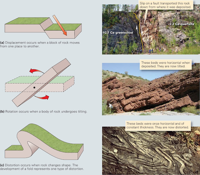
Triode valves generate largely even harmonics, while pentode circuits give odd ones, often considered less musical, but deeper and richer.
Saturation is usually used subtly, rather than pushed to the point of obvious distortion - though it’s always an option!
3. Clipping
Many types of distortion employ clipping behaviour, but when we talk about clipping in music production, we’re usually referring to basic hard and soft clipping. While pure digital clipping can sound harsh, a dedicated soft/hard clipper can reduce peaks invisibly when used moderately.
In the mix, clipping is useful for keeping signal levels in check, and great for transient-heavy sources.
4. Overdrive
Guitar overdrive pedals like the Ibanez Tube Screamer apply mild distortion, often coupled with EQ/filtering and a level boost, all designed to overload the input of the amplifier they’re connected to, adding aggression to a sound which could already be quite ‘hot’.
Heard in isolation, overdrive has a basic, crunchy timbre that retains dynamics - half way between the subtlety of saturation and all-out distortion.
5. Fuzz
Fuzz is basically very strong clipping, usually used as a guitar effect. It adds harmonic distortion and massive sustain, and obliterates dynamics. A filter to roll off the treble can make it more versatile.
One of the all-time classic fuzz boxes, Electro-Harmonix’ Big Muff - of which Universal Audio’s Bermuda Triangle is a great emulation - has just three controls: Sustain, (output) Volume and Tone (filter).
6. Distortion
Confusingly, there is a distortion type called ‘distortion’, derived from the world of guitar pedals. Most associated with heavy guitar music like punk and metal, distortion may incorporate multiple EQ, filtering and clipping stages, arranged and tuned to give extreme results while retaining articulation.
Unlike overdrive, distortion pedals are intended to largely create the distorted tone by themselves.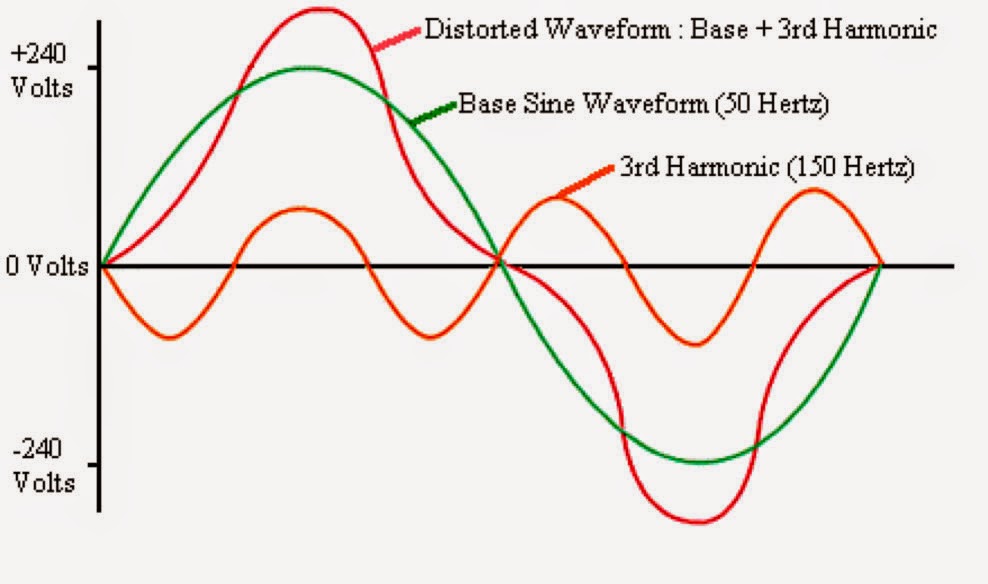
7. Guitar amp and cabinet
Guitar distortion heard on its own can sound very fizzy and harsh. The guitar sounds we’re used to hearing come from a microphone placed in front of a speaker cabinet in a real room, all three of which heavily colour the frequency response. So, for an authentic tone, these aspects must be simulated too, and many plugins offer this.
8. Bitcrushing
Bit-depth reduction gives us the crunchy sound of old-school sampling and vintage home computers. It adds grit and edge, which can help sounds cut through busy mixes. It also adds a hissing sound, noticeable on signals like reverb tails, so you might want to gate signals before bitcrushing and apply reverb afterwards. Unless that’s the old-school, sampled vibe you’re after!
9. Sample rate reduction
Sample-rate reduction decreases the temporal ‘resolution’ of the digital signal. The most recognisable result is a kind of atonal ringing with a metallic edge. You can roughly tune this ringing by changing the sample rate, or modulate it for distinctive riffs and digital effects.
Modulation of the sample rate is often used as a sound effect in modern sci-fi soundtracks.
Computer Music issue 228 on sale now
Think you know distortion? Think again! To give your sounds and mixes the heat they truly deserve, you can't just pile on the plugins and hope for the best.
Check out Computer Music issue 228 to find out how distortion really works, and what you've been missing out on in the quest for professional, attention-grabbing sounds. Plus: FREE Distortion Plugin – 57 more VST/AU plugins – 916 Retro House Samples!
Computer Music magazine is the world’s best selling publication dedicated solely to making great music with your Mac or PC computer. Each issue it brings its lucky readers the best in cutting-edge tutorials, need-to-know, expert software reviews and even all the tools you actually need to make great music today, courtesy of our legendary CM Plugin Suite.
Types of signal distortion during digitization and ways to minimize them
Quantization noise
Distortions that almost inevitably occur during the digitization of sound and its subsequent restoration are called "quantization noise":
red line - original analog signal,
green line - digital signal represented by discrete values,
blue line is the difference between the original signal and its digital representation, i.e. quantization error. nine0012
This is the conditional difference between the original analog signal and its digital copy, which, when inverted, generates additional frequency components. They do not have a fundamental frequency (i.e., the energy is distributed randomly over them), so they are heard in the form of noise.
To combat this phenomenon, first of all, preliminary low-pass filtering is used, i.e. suppression of high-frequency spectral components of the signal. In addition, techniques such as Dithering and Noise-shaping are used. nine0005
Dithering
Dithering (dithering) is mixing pseudo-random noise with a specially selected spectrum into the primary signal. The dithering technique is applied not only to sound, but also to images (including video), and here its effect is very clear:
Photo 1. Original image.
Photo 2. Original image converted using the HTML Colors palette (216 colors). Areas of solid color and a general loss of detail are noticeable. nine0005
Photo 3. Original image converted using the HTML Colors palette and Flood-Steinberg dithering. Despite the same palette, this image has more detail.
(https://commons.wikimedia.org/wiki)
Sound dithering:
it does not mask distortions, but prevents them. Mixed artificial noise, unlike "digital noise", does not correlate with the signal, so it does not distort it, but only creates a background that is not very noticeable to the ear. nine0005
Noise-shaping
There is a more sophisticated method called noise shaping.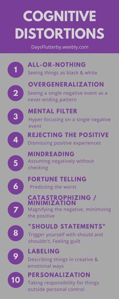 It consists in the fact that the difference between the quantized and the original signals is passed through a filter and added to the next signal sample. By varying the frequency response of the filter, one can achieve the desired quantization error spectrum. Most often, the quantization error is pushed into the high frequency and ultrasonic range, where it will be less audible. With noise shaping, the overall power of the quantization error increases (compared to dithering), but its subjective loudness decreases. nine0005
Example
Let's look at a 750 Hz sine wave that was sampled at 48 kHz and 4 bits without dithering or noise shaping. In this case, every 64 samples there is a rounding error, visible as a harmonic with an amplitude of up to -40 dB in relation to the fundamental tone:
The same sinusoid with dither but without noise shaping. Note that the overall noise intensity has increased, but none of the harmonics reach -60dB:
The same sine wave with dither and noise shaping. Note that the noise is even quieter (−80 dB) in the 4 kHz region where hearing is most sensitive:
Aliasing
the phenomenon is called aliasing (frequency substitution, frequency masking, aliasing). As you can see from the illustration, it occurs when the sampling rate (sampling rate) is insufficient, so to eliminate it, you can either increase the sampling rate, or apply a low-pass filter that will suppress frequencies above the Nyquist frequency:
As an illustration, here are 4 waves, each digitized with 6 different sampling rates. Two waves retain their appearance at all 6 sample rates, while the other two show an increase in aliasing distortion at lower sample rates:
Sound example. Sawtooth wave at 440, 880 and 1760 Hz. First with a filter applied, then without, in which case aliasing is clearly audible:
Jitter
Jitter is a random deviation of the transmitted signal that occurs due to the instability of the master oscillator:
6.
 2. Distortion in amplifiers | Electrical engineering
 The main quality indicator of the amplifier is the accuracy of reproduction of the form of the amplified signal. In an ideal amplifier, the output waveform should exactly match the input waveform. The deviation of the shape of the output signal from the shape of the signal applied to its input is called distortion .
There are two types of distortion in amplifiers - linear and non-linear. Both types of distortion change the shape of the input signal, but the reasons for their appearance are different.
Linear distortion is due to the dependence of the modulus of the voltage or current gain, as well as the phase shift between input and output values, on the frequency of the input signal. Linear distortion can be divided into frequency and phase.
The shape of a complex signal at the output of an amplifier operating in a linear mode will differ from the input if the harmonic components of the input signal are amplified differently in the amplifier, and also if the phase shifts introduced by the amplifier are different for individual harmonic components. The changes in the shape of the output signal caused by these reasons are called frequency and phase distortions, respectively.
Frequency distortion are distortions due to changes in the value of the gain at different frequencies. The ideal frequency response should have the same gain over the entire operating frequency range. The real characteristic has "blockages" at frequencies close to the boundaries of the operating frequency range. The decrease in the gain at lower frequencies is explained by the increase in the capacitance of the isolation capacitors
x C = 1 / wC
as the signal frequency decreases. nine0005
The decrease in K U at higher frequencies is due to the influence of parasitic collector-base, collector-emitter and base-emitter capacitances, as well as parasitic capacitances that occur during installation. These capacitances at high frequencies short out the transistors and reduce signal gain.
To quantify the frequency distortion use frequency distortion factor (M), equal to the ratio of the gain at medium frequencies (K cf ) to the gain at a given frequency (K ¦ ):
M = K cf. / K ¦ .
Since the greatest frequency distortion occurs at the boundaries of the operating range, when calculating the amplifier, the coefficients of frequency distortion at the lowest and highest frequencies are set, i.e.
M H = K CP / K H and M in = K CP / K in . nine0005
Frequency distortion in the amplifier is always accompanied by the appearance of phase distortion. When amplifying a sinusoidal signal with a constant frequency, linear distortion does not play a big role: at one specific frequency, sufficient amplification can always be achieved, and phase shifts can be compensated.
The problem of linear distortion occurs when the signal has a complex shape. For such a signal, phase-frequency distortions are no less, and often more significant, than amplitude-frequency ones. nine0005
Phase distortions do not affect the spectral composition and the amplitude ratio of the harmonic components of a complex signal, but cause a change in its shape as a result of various phase shifts that occur in individual signal components after passing through the amplifier.