Which axis of the dsm iv includes physical conditions
Diagnostic and Statistical Manual of Mental Disorders (DSM)
The Diagnostic and Statistical Manual of Mental
Disorders (commonly abbreviated as DSM) is a book
published by the American Psychiatric Association, that
is used to officially diagnose mental disorders.
WHAT IS THE MOST CURRENT EDITION OF THE
DSM?
The most current edition (published in 2013) of the DSM
is the DSM-5. This stands for the DSM (5th edition)
Text Revision. The 4th edition was published in 1994
and was revised in 2000.
FEATURED BOOK: Diagnostic and Statistical Manual of Mental Disorders - 5th ed.
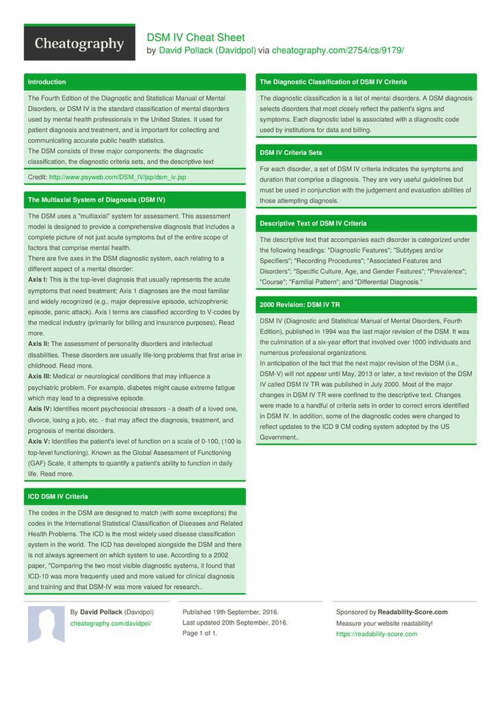
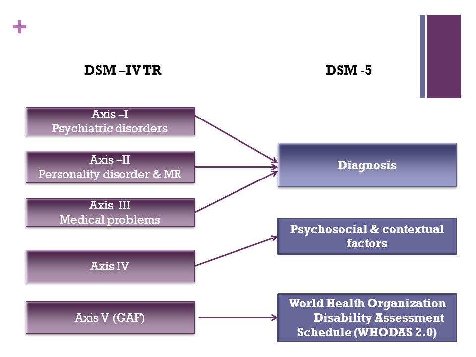
WHAT IS THE MULTIAXIAL CLASSIFICATION SYSTEM OF THE DSM?
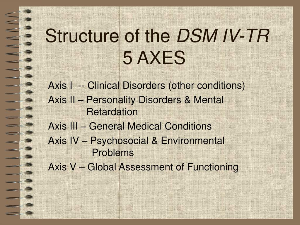
When using the DSM-5 to diagnose a patient, clinicians evaluate the patient on five
separate axes, or branches of information, that are based on sets of criteria. This is
known as the multiaxial (more than one axis) classification system. Axis I and Axis II
include all of the mental disorders. Mental disorders diagnosed on Axis I are those that
cause the patient significant impairment and are the focus of the patient's treatment. The
exception is personality disorders and mental retardation, which are diagnosed on Axis II.
A person can have more than one diagnosis on Axis I. However, the diagnosis that is
listed first on Axis I should be the one that represents the patient's main area of difficulty.
Diagnoses on Axis III are general medical conditions that are
potentially important in understanding or managing the patient's
mental disorder. An example of a diagnosis on Axis III would be
multiple sclerosis. Axis IV consists of stressors in the person's
environment or social setting that may affect the diagnosis,
treatment, and outlook of the patient's mental disorder. An example
would be death of a family member. Finally, Axis V is a rating given
by the clinician on a scale known as the Global Assessment of
Functioning (GAF). The score on the GAF indicates the patient's
overall level of functioning. Scores range from 1 to 100, with 100
being superior functioning. A score of 0 means that there was not
enough information to give an adequate score.
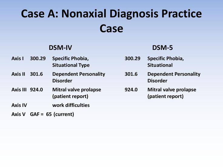
Keeping the above description in mind, here is an example of what a diagnosis may look like using the
DSM in a clinician's report:
AXIS I: Major Depressive Disorder
AXIS II: Dependent Personality Disorder
AXIS III: Mesothelioma
AXIS IV: Death of a family member
AXIS V: Current GAF: 60 (moderate symptoms).
IS THE DSM ALWAYS RIGHT?
No. A very important thing to keep in mind is that the criteria that are used to define mental disorders in
the DSM are based on a majority view of consultants and contributors in mental health care, many of
which are psychiatrists and some of which are psychologists. However, a majority view is not always
correct and the criteria used to diagnose mental disorders in one edition of the DSM are often changed in
future editions. Also, some mental disorders have been completely removed from the DSM. For example,
in 1973, homosexuality was removed from the DSM as a mental disorder.
WHAT ELSE IS IN THE DSM?
The DSM contains information about each mental disorder such as associated features of the disorder,
what age the disorder usually begins, whether the disorder is more likely to occur in males or females,
what types of impairments and complications are usually found in the disorder, what are risks for
developing the disorder, what patterns are found in the families of people with the mental disorder,
information on how to figure out the difference between similar mental disorders, the percent of people
that have the disorder, and more.
HOW MANY MENTAL DISORDERS ARE IN THE DSM?
There are over 300 mental disorders listed in the DSM-IV TR.
WHAT ARE THOSE CODE NUMBERS IN THE DSM?
Each mental disorder and physical disorder listed in the DSM is identified with a specific number. This
This
number matches those published by the World Health Organization's International Statistical Classification
of Diseases & Related Health Problems . This is commonly abbreviated and referred to as ICD. The ICD
is another classification system, used to classify mental and physical disorders. The most current version
is ICD-10.
WHAT ABOUT EARLIER EDITIONS OF THE DSM?
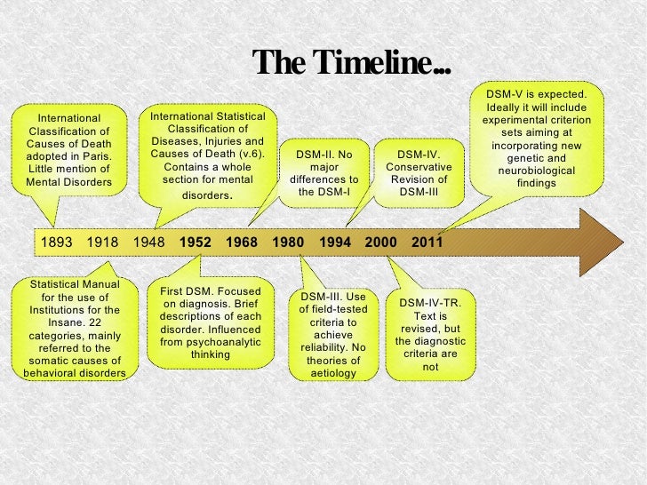
The original DSM was published in 1952 as a way to encourage clinicians to use the same standards to
diagnose mental illness and was partially based on the ICD-6 (6th edition). See the answer to the last
question for a description of ICD. The original DSM contained definitions of all named mental disorders but
did not list any criteria for diagnosing these disorders. The original DSM was influenced by the theories of
Sigmund Freud, but the names of many of the mental disorders had the word "reaction" after them, a term
used often by a psychologist named Adolf Meyer.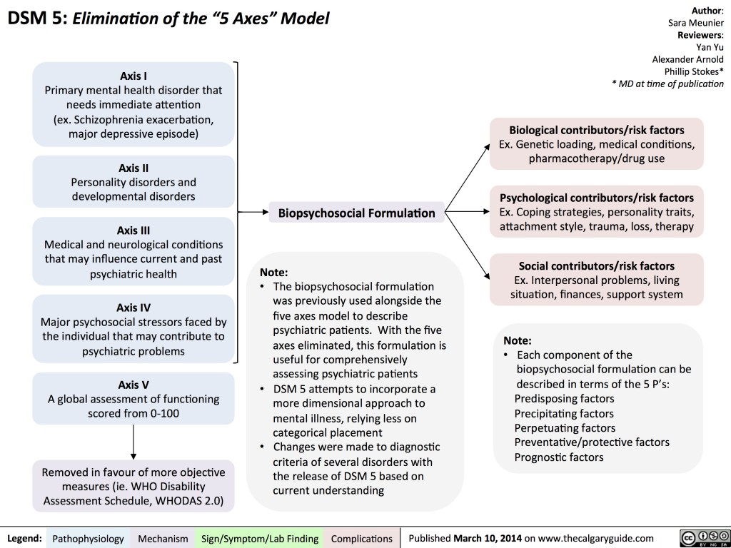
The DSM-II (2nd edition) was published in 1968. Freud's theories still influenced this edition, but the use of
the term "reaction" was dropped for the names of the mental disorders. Freud's theories were no longer a
major part of the DSM when the third edition (DSM-III) was published in 1980. The DSM-III was the first
time that clear criteria were stated in the DSM for diagnosing mental disorders. The DSM-III also saw the
introduction of the multi-axial classification system discussed above. Some clarifications and
improvements were published in a revised version of the third edition (DSM-III-R), published in 1987.
The DSM-IV was published in May on 1994. The major change in this edition is that it renamed a category
of mental disorders known as "Organic Mental Syndromes and Disorders" to "Delirium, Dementia, and
Amnestic and Other Cognitive Disorders." This change was made so that people did not assume that
disorders not listed in the category of "Organic Mental Syndromes and Disorders" were not due, at least in
part, to abnormal functioning of the brain or some other parts of the body (which is what the word "organic"
refers to).
The Diagnostic and Statistical Manual of Mental Disorders
The "bible" of diagnoses, the Diagnostic and Statistical Manual of Mental Disorders, Fourth Edition-Text Revision, known as the DSM-IV-TR and published by the American Psychiatric Association is extensively used by psychiatrists, psychologists, social workers and most other mental health professionals in the U.S., Canada and abroad to provide a common nomenclature for diagnostic purposes and for communicating about mental disorders. (In Europe the International Classification of Diseases (ICD-10), published by the World Health Organization, is more commonly used. The U.S. Department of Health and Human Services is
FIND MORE ARTICLES
moving towards utilizing ICD-10 codes resulting in compatibility between the two resources). The DSM-IV-TR provides a common language for illnesses of emotional and psychological origin. Its success and wide acceptance is reflected in its translation into over twenty languages including Japanese, French, Turkish, Greek and Arabic.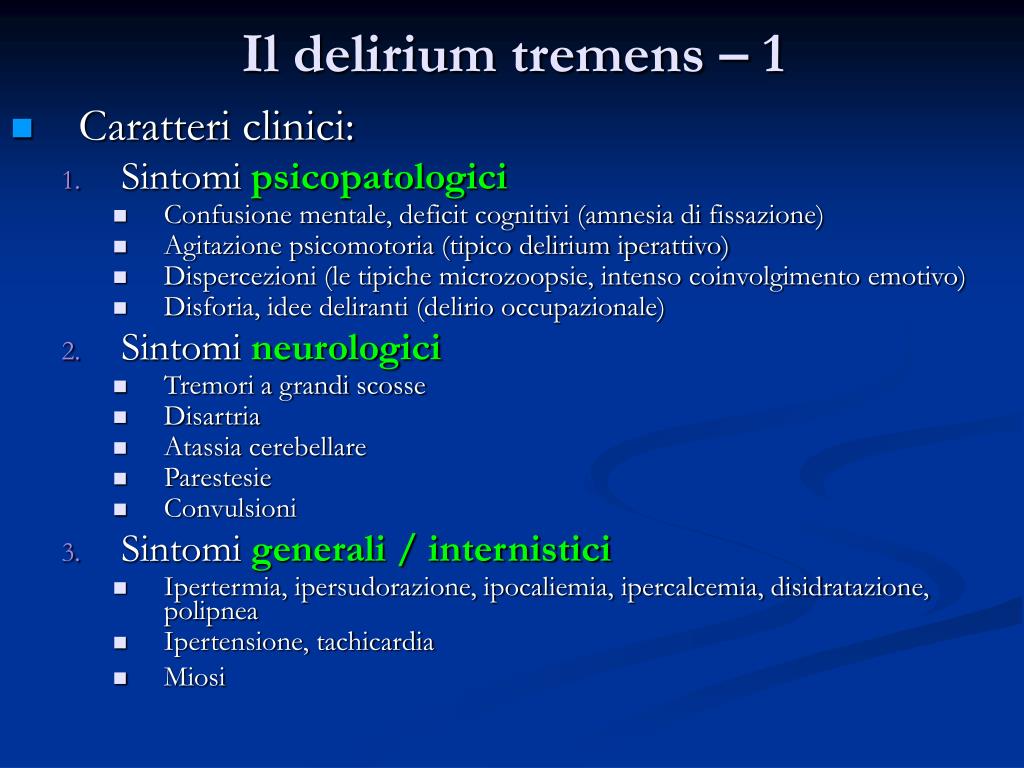 The first edition, the DSM-I, appeared in 1952. It was superseded in 1968 by the DSM-II, which in turn was replaced, by the DSM-III in 1974, the DSM-IV in 1994, and currently, the DSM-IV-TR in 2000. The DSM-V is scheduled to supplant the current DSM-IV-TR in 2010.
Initially, about 60 different disorders were listed with little distinction between normal and abnormal as disorders existed along a continuum and were considered reactions to environmental stressors. The major distinction was between psychosis—a severe mental condition involving a break with reality— and neurosis—a disorder usually involving anxiety and depression. One applying the early DSM diagnoses may have found that no one was normal. When the DSM-III was published, there was a shift away from this binary classification to characterization of behaviors. Mental disorders today are conceptualized as behavioral or psychological syndromes that occur in a person in response to distress, disability or suffering, not merely the expectable or usual response to a particular event. Disorders are described in descriptive and behavioral terms and are not reflective of a particular theory or discipline. Additionally, a mental disorder is assumed not to be a discrete entity. People described as having the same disorder may not be alike although they minimally meet the defining features of the same emotional illness.
The DSM-IV-TR, properly utilized, affords a multiaxial diagnosis. Axis-I allows the diagnosis of major mental disorders such as Manic-Depressive Illness, Schizophrenia, Substance Abuse, Post-traumatic Stress and organically based mental illness. Axis-II is reserved for personality and developmental disorders. A personality disorder is diagnosed when personality traits become dysfunctional and maladaptive causing impairment in the individual's functioning. Often, personality disorders can be quite severe and debilitating. Axis-III is used to indicate the presence of physical conditions that potentially affect psychological functioning. Axis-IV assesses the severity of psychosocial stressors that may have contributed to the development or exacerbation or recurrence of a mental disorder.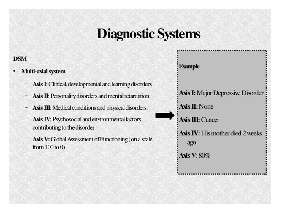 Axis-V permits an assessment of the individual's overall level of psychological, social and occupational functioning. Used correctly, the DSM-IV-TR helps us to understand the individual in context and allows ready communication between mental health professionals. It further serves to direct treatment including the use of medication.
The DSM is not without problems or controversy. One abiding issue is the difference in the description of diagnosis between the DSM-IV-TR and ICD-10. Clinicians describing a patient must read from the same “playbook” if they want to properly serve their patient. Another issue is that every decade, the DSM is revised whereby diagnostic descriptions may be modified, new diagnoses added, and obsolete ones deleted. In the DSM-II, homosexuality was listed as a disorder and Posttraumatic Stress Disorder was absent. As good as the current DSM may be in allowing clinicians to characterize mental conditions, the effect of “labeling” an individual may blind the psychologist from identifying other factors affecting the patient, or cause the clinician to conceptualize all of the client’s behavior from a single framework. Nonetheless, proper diagnosis, even if not fully comprehensive and imperfect, fosters effective treatment that best helps those in need.
Alternatives to the DSM-IV-TR, besides the ICD-10, include the Diagnostic Classification of Mental Health and Development Disorders of Infancy and Early Childhood (DC:03-R) designed for diagnosing difficulties in very young children published by Zero to Three, and the Psychodynamic Diagnostic Manual (PDM, 2006) published by the Alliance of Psychoanalytic Organizations which is based upon neuroscience, treatment outcome studies and psychoanalytic thought.
The Diagnostic and Statistical Manual of Mental Disorders is published by the American Psychiatric Association.
By Steven N. Shapse, Ph.D.
Expert Website: http://shapse.com/wp
Call (781) 259-0283
ABOUT THE AUTHOR: Steven N. Shapse, Ph.D.
Dr. Steven N. Shapse is a Licensed Psychologist in the Commonwealth of Massachusetts.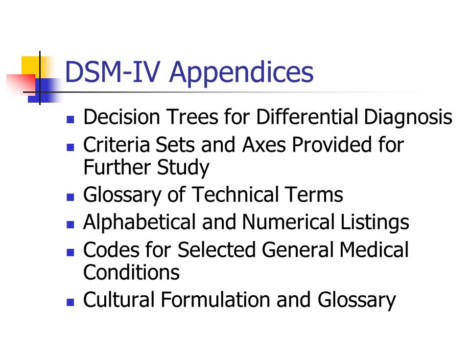 He has over 30 years experience in the field of psychology as both a clinician and teacher which includes over twenty years as a forensic expert, psychometrist and child custody evaluator. He regularly presents at state and national associations, and often teaches at the Massachusetts School of Professional Psychology. He is a Senior Supervisor at the Justice Resource Institute Trauma Center and a principal founder and Past-President of the Massachusetts Association of Guardians ad Litem.
Copyright Steven N. Shapse, Ph.D.
Disclaimer: While every effort has been made to ensure the accuracy of this publication, it is not intended to provide legal advice as individual situations will differ and should be discussed with an expert and/or lawyer.For specific technical or legal advice on the information provided and related topics, please contact the author.
Deploying a two-node clustered file server
- Article
- Reading takes 17 minutes
Applies to: Windows Server 2022, Windows Server 2019, Windows Server 2016
A failover cluster is a group of independent computers that work together to increase the availability of applications and services.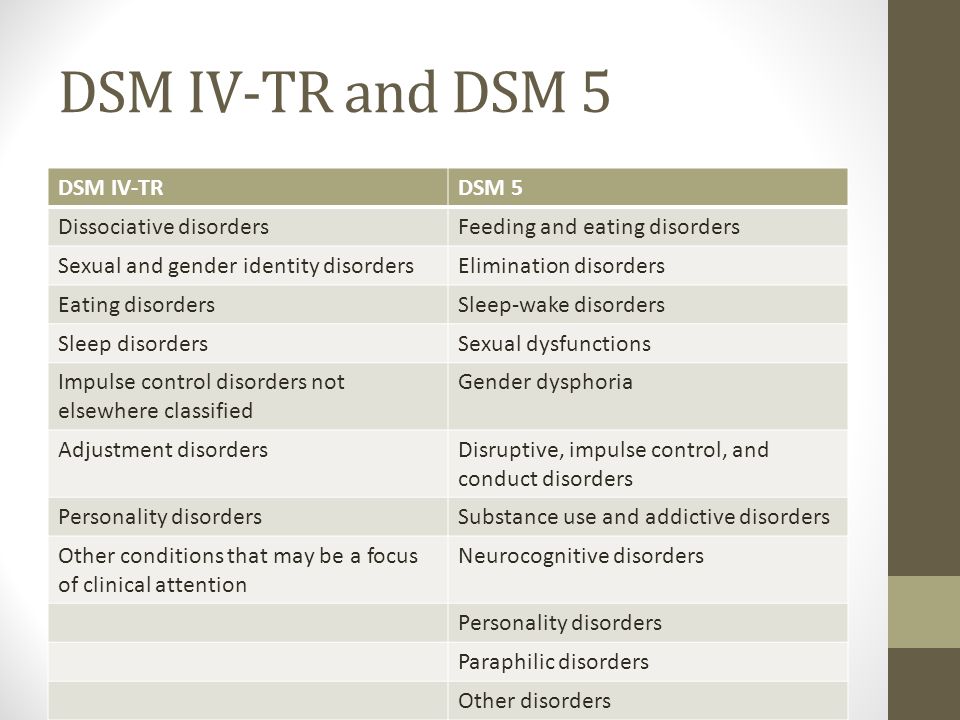 Clustered servers (called "nodes") are connected by physical cables and software. When one of the nodes in the cluster fails, its functions are immediately transferred to another node (this process is called failover). Users experience minimal disruption to the service. For information about using Failover Clustering in Azure Stack HCI, see Create an Azure Stack HCI cluster using Windows Admin Center.
This guide describes the steps for installing and configuring a two-node general purpose file server failover cluster. By creating the configuration in this guide, you can learn about failover clusters and familiarize yourself with the interface of the Manage Failover Cluster snap-in in Windows Server 2019 or Windows Server 2016. in a variety of roles, including file server, Hyper-V server, or database server roles, and provide high availability for various services and applications. This guide describes how to set up a two-node file server cluster.
A failover cluster typically includes a storage unit that is physically connected to all servers in the cluster, although any given storage volume is accessed by only one server at a time. The following diagram shows a two-node failover cluster connected to a storage unit.
Volume storage service or logical unit numbers (LUNs) provided to nodes in a cluster should not be provided to other servers, including servers in another cluster. The following diagram shows the following.
Note that for maximum availability of any server, it is important to follow server management best practices, such as carefully managing the physical environment of servers, reviewing software changes before they are fully implemented, and carefully monitoring software updates and configuration changes on all clustered servers.
The following scenario describes how you can set up a file server failover cluster. Shared files reside on cluster storage, and any clustered server can act as a file server that shares them.
Failover Clustering Shared Folders
The following list describes the shared folder configuration features that are integrated with Failover Clustering.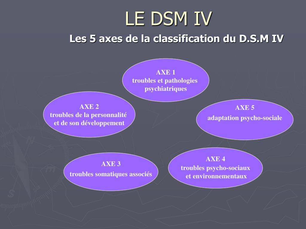
-
Display is limited to clustered shares only (not combined with non-clustered shares). If a user browses public folders by specifying the path of a clustered file server, only public folders that are part of a specific file server role are displayed. It will exclude non-clustered shared folders and shared folders in individual file server roles that may be on a cluster node.
-
Access-based enumeration. Access-based enumeration can be used to hide the specified folder from the users view. Instead of allowing users to see the folder but not access it, you can prevent them from seeing the folder at all. Access-based enumeration can be configured for a clustered public folder in the same way as for a non-clustered public folder.
-
Offline access: Offline access (caching) for a clustered shared folder can be configured in the same way as for a nonclustered shared folder.
-
Clustered disks are always recognized as part of a cluster.
 Regardless of whether you are using the Failover Cluster interface, Windows Explorer, or the Share Management snap-in and Storage Service, Windows recognizes whether a drive has been assigned to cluster storage. If such a drive is already configured in Failover Cluster Management as part of a clustered file server, you can use any of the previously mentioned interfaces to create a shared folder on the drive. If such a drive has not been configured as part of a clustered file server, you cannot mistakenly create a file share on it. Instead, the error indicates that the disk must first be configured as part of a clustered file server before it can be shared.
 -
Network File System Services Integration: The File Server role in Windows Server includes an optional role service called Services for Network File System (NFS). By installing the Role Service and configuring Shared Folders with Services for NFS, you can create a clustered file server that supports UNIX-based clients.
Requirements for a two-node failover cluster
To enable a failover cluster in Windows Server 2016 or Windows Server 2019was considered an officially supported solution by Microsoft, the solution must meet the following criteria.
-
All hardware and software components must meet certification requirements for the corresponding OS logo. For Windows Server 2016, this is the Certified for Windows Server 2016 logo. For Windows Server 2019, this is the "Certified for Windows Server 2019" logo. For more information about which hardware and software systems are certified, visit the Microsoft Windows Server Directory site.
-
A fully configured solution (servers, network, and storage) must pass all tests in the validation wizard that is part of the Failover Cluster snap-in.
A two-node failover cluster requires the following.
-
Servers: We recommend that you use the appropriate computers with the same or similar components.
 Servers for a two-node failover cluster must be running the same version of Windows Server. They must also have the same software updates (patches).
 -
Network adapters and cable: Network hardware, like other components in a failover cluster solution, must be compatible with Windows Server 2016 or Windows Server 2019. When using iSCSI, network adapters must be dedicated for networking or iSCSI, not for both. Avoid single points of failure in the network infrastructure connecting cluster nodes. This can be done in several ways. Cluster nodes can be connected by several different networks. It is also possible to connect cluster nodes into a single network based on grouped network adapters, redundant switches and routers, and similar equipment without single points of failure.
Note
If the cluster nodes are connected to the same network, the network will pass a redundancy request in the Validate Configuration Wizard. However, the report will contain a warning that the network should not have a single point of failure.
-
Device controllers or appropriate storage adapters:
- Serial-attached SCSI or Fiber Channel: When using daisy-chained SCSI or Fiber Channel on all clustered servers, all storage stack components must be identical. The software multi-path I/O (MPIO) and the dsM software components need to be identical. It is recommended that the storage controllers, i.e. bus adapter (HBA), HBA drivers, and HBA firmware attached to the cluster storage, be identical. When using different HBAs, check with your storage vendor to see if they provide supported or recommended configurations.
- Iscsi: When using iSCSI, each clustered server must have one or more NICs or host bus adapters dedicated to iSCSI storage. The network used for iSCSI cannot be used for networking. All clustered servers must have the same network adapters to connect to the iSCSI target storage. Gigabit Ethernet or higher bandwidth adapters are recommended.

-
storage service. You must use shared storage certified for Windows Server 2016 or Windows Server 2019.
For a two-node failover cluster, storage must contain at least two separate volumes (LUNs) if a quorum witness disk is used. A disk witness is a disk in the cluster storage that holds a copy of the cluster configuration database. In this example of a two-node cluster, the quorum configuration would be Node and Disk Majority. Node and Disk Majority means that the nodes and disk witness contain copies of the cluster configuration, and the cluster has a quorum if a majority (of three) of these copies are available. The other volume (LUN) will contain files that are provided to users.
The storage requirements are as follows.
- To use the native disk support included with the failover cluster feature, use basic disks rather than dynamic disks.
- It is recommended to format the partitions using NTFS (the partition must be NTFS for the witness disk).

- You can use Master Boot Record (MBR) or a GPT partition table to partition a disk.
- The storage must respond correctly to certain SCSI commands. The storage must comply with the SCSI Primary Commands-3 (SPC-3) standard. In particular, the repository must support persistent reservations as specified in the SPC-3 standard.
- The miniport driver used for storage must work with the Microsoft Storport storage driver.
Deploying Storage Area Networks with Failover Clustering
When deploying a Storage Area Network (SAN) with Failover Clustering, consider the following guidelines.
-
Verify storage certification: Use the Windows Server Directory site to verify that the vendor's storage, including drivers, firmware, and software, is certified for Windows Server 2016 or Windows Server 2019.
-
Isolate storage devices, one cluster per device: Servers from different clusters should not be able to access the same storage device.
 In most cases, the LUN used for one set of servers in a cluster must be isolated from all other servers using luN masquerading or zoning.
 -
Consider using multipath I/O software: In a highly available storage fabric, you can deploy failover clusters with multiple host bus adapters using multipath I/O software. This provides the maximum level of redundancy and availability. The multipath solution must be based on multipath input/output (MPIO). The storage hardware vendor may provide a FOR MPIO device module for your hardware, although Windows Server 2016 and Windows Server 2019include one or more DSMs as part of the operating system.
Network infrastructure and domain account requirements
You will need the following network infrastructure for a two-node failover cluster and an administrator account with the following domain permissions:
-
Network settings and IP addresses: When using identical network adapters the network also uses identical communication settings for these adapters (for example, speed, duplex mode, flow control, and media type).
 Also, compare the settings on the network adapter and the switch it connects to and make sure they don't conflict.
 If there are private networks that are not routed to the rest of the network infrastructure, ensure that a unique subnet is used for each of these private networks. This is necessary even if each network adapter has a unique IP address. For example, if the central office has a cluster node that uses the same physical network, and the branch office has another node that uses a separate physical network, do not specify 10.0.0.0/24 for both networks, even if each adapter has a unique IP address.
For more information about network adapters, see "Hardware requirements" for a two-node failover cluster earlier in this guide.
-
DNS: The servers in the cluster must use the Domain Name System (DNS) for name resolution. You can use the DNS dynamic update protocol.
-
Domain role: All servers in a cluster must be in the same Active Directory domain.
 We recommend that all clustered servers have the same domain role (member server or domain controller). The recommended role is Member Server.
 -
Domain controller: We recommend that clustered servers be members. If so, you will need an additional server that acts as a domain controller in the domain that contains the failover cluster.
-
Clients: Optionally, for testing purposes, you can connect one or more network clients to the failover cluster you are creating and observe the effect on the client when a clustered file server is moved or fails over from one cluster node to another.
-
Cluster administration account: The first time you create a cluster or add servers to it, you must be logged on to the domain with an account that has administrative rights and permissions on all servers in that cluster. It does not have to be a member of the Domain Admins group. For example, this could be a domain user account that is a member of the Administrators group on each clustered server.
 Also, if the account is not a domain administrator account, then the account (or the group of which the account is a member) must be granted permissions to create computer objects and permission to read all properties in the OU of the domain where the domain OU will reside.
Steps to install a two-node file server cluster
To install a two-node file server failover cluster, you must complete the following steps.
Step 1: Connect the cluster servers to the network and storage
Step 2: Install the failover cluster component
Step 3: Verify the cluster configuration
Step 4: Create the cluster
If you have already installed cluster nodes and want to set up a file server failover cluster, see the instructions for configuring a two-node file server cluster later in this guide.
Step 1: Connect the cluster servers to the network and storage
For a failover cluster network, avoid using single points of failure. This can be done in several ways. Cluster nodes can be connected by several separate networks. It is also possible to connect the cluster nodes to a single network created with pooled NICs, redundant switches, redundant routers, or similar equipment that removes individual points of failure (if you are using a network for iSCSI, you must create this network in addition to other networks) .
For a two-node file server cluster, at least two volumes (LUNs) must be provisioned when connecting servers to cluster storage. If necessary, you can provide additional volumes for thorough testing of the configuration. Do not provide clustered volumes to servers that are not in a cluster.
Connecting cluster servers to networks and storage
-
Review the hardware requirements for a two-node failover cluster and the network infrastructure and domain account requirements for a two-node failover cluster earlier in this guide for detailed networking information. .
-
Connect and configure the networks that will use the servers in the cluster.

-
If the test configuration includes clients or a non-clustered domain controller, verify that these computers can connect to the clustered servers through at least one network.
-
Follow the manufacturer's instructions to physically connect the servers to the storage.
-
Make sure that the disks (LUNs) you want to use in the cluster are available to (and only) the clustered servers. You can use any of the following interfaces to provision disks or LUNs:
-
interface provided by the storage manufacturer;
-
If you are using iSCSI, the corresponding iSCSI interface.
-
-
If you have purchased software that controls the format or function of a drive, follow the vendor's instructions on how to use the software with Windows Server.
-
On one of the servers that the cluster requires, click the Start button, select Administrative Tools, Computer Management, and Disk Management.
 (If the User Account Control dialog box appears, verify that the displayed action is the one you want, and then click Continue.) Verify that the cluster disks are visible in Disk Management.
 -
If you need more than 2 terabytes of storage, and you use the Windows interface to control the disk format, convert the disk partition type to a GPT partition table. To do this, back up all the data on the disk, delete all volumes on the disk, and then in Disk Management, right-click the disk (not a partition) and select "Convert to GPT Disk". If the volume is less than 2 terabytes, then instead of the GPT partition table, you can use a type of partition called the master boot record (MBR).
-
Check the formats of any provisioned volumes or LUNs. NTFS is recommended for NTFS format (NTFS must be used for the witness drive).
Step 2: Install the File Server Role and Failover Clustering Feature
This step will install the File Server Role and Failover Clustering Feature.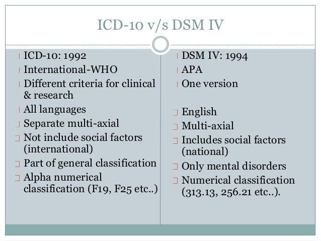 Both servers must be running Windows Server 2016 or Windows Server 2019.
Using Server Manager
-
Open Server Manager and in the drop-down list "Manage " select "Add roles and features ".
-
If the window "Before you start" opens, click the button "Next ".
-
In , select as installation type role-based installation or and feature-based installation, click Next .
-
Make sure that a server is selected from the server pool , the computer name is highlighted and click the "Next " button.
-
For the server role in the list of roles, open File Services , select "File Server " and "Next ".
-
Select Failover Clustering in the feature list.
 A pop-up dialog will open with a list of installed administration tools. Leave all items selected and press button "Add components " and "Next ".
 -
On the Confirmation page, click Install.
-
After installation is complete, restart your computer.
-
Repeat the steps on the second computer.
Using PowerShell
-
Open a PowerShell session as an administrator by right-clicking the Start button and then selecting Windows PowerShell (Admin).
-
To install the file server role, run the following command:
Install-WindowsFeature -Name FS-FileServer
-
To install the Failover Clustering feature and its management tools, run the following command:
Install-WindowsFeature -Name Failover-Clustering -IncludeManagementTools
-
Once completed, you can check if they are installed using the commands:
Get-WindowsFeature -Name FS-FileServer Get-WindowsFeature -Name Failover-Clustering
-
After verifying their installation, restart the computer with the command:
Restart Computer
-
Repeat the steps on the second server.
Step 3: Verify the cluster configuration
It is highly recommended that you verify the configuration before creating the cluster. Validation helps ensure that the server, network, and storage configurations meet a set of specific requirements for failover clusters.
Using Failover Cluster Manager.
-
In Server Manager , select the Service dropdown and select Failover Cluster Manager .
-
In Failover Cluster Manager navigate to the middle column under Manage and select "Verify Configuration".
-
If window "Before starting" 9 opens0084 , press the button "Next ".
-
In the server or cluster selection window add the names of the two computers that will be the nodes of the cluster. For example, if the names are NODE1 and NODE2, enter the name and click the "Add " button.
 You can also click the Browse button to look up names in Active Directory. After listing both servers in section "Selected servers " click on the button "Next ".
 -
In window "Test parameters " select "Perform all tests (recommended) " and "Next ".
-
On the confirmation page you will get a list of all the tests it will check. Press the button "Next", and the tests will begin.
-
When completed, after running the tests, page of summary will appear. To view help topics to help you interpret the results, click "Additional information about cluster validation tests".
-
On the Summary page, click View Report to view test results. Make the necessary changes to the configuration and rerun the tests.
To view test results after closing the wizard, see SystemRoot\Cluster\Reports\Validation Report and time. html .
 -
To view help topics about validating a cluster after closing the wizard, in the Manage Failover Clustering section, click Help, click Help Topics, select the Content tab, expand the Failover Cluster Help content, and then click Validate Failover Cluster Configuration ".
Using PowerShell
-
Open a PowerShell session as an administrator by right-clicking the Start button and then selecting Windows PowerShell (Admin).
-
To check computers (for example, computer names NODE1 and NODE2) for failover clustering, run the following command:
Test-Cluster -Node "NODE1","NODE2"
-
To view test results after the wizard is closed, view the specified file (in SystemRoot\Cluster\Reports), then make the necessary configuration changes and rerun the tests.
For more information, see "Verify Failover Cluster Configuration".
Step 4: Create a Cluster
Next, a cluster will be created from the computers and configuration you have.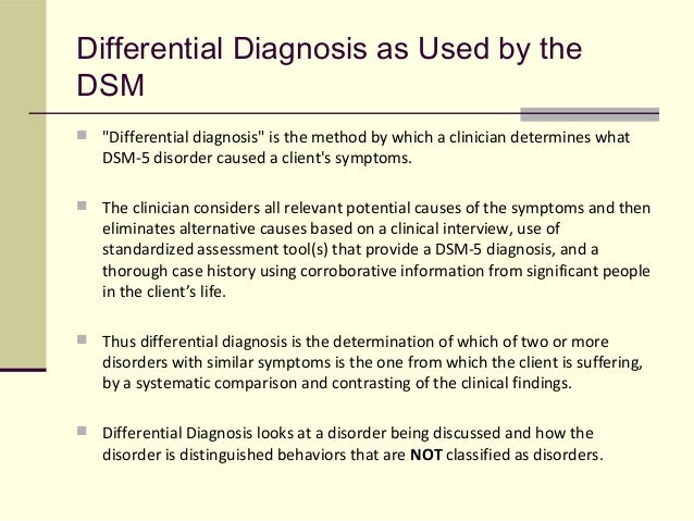
Using Failover Cluster Manager.
-
In Server Manager , select the Service dropdown and select Failover Cluster Manager .
-
In the Failover Cluster Manager , navigate to the middle column under Manage and select "Create Cluster ".
-
If the window "Before you start" opens, click the button "Next ".
-
In the Server Selection window , add the names of the two computers that will be the nodes of the cluster. For example, if the names are NODE1 and NODE2, enter the name and press the 9 button0083 "Add ". You can also click the Browse button to look up names in Active Directory. After listing both servers in section "Selected servers " click on the button "Next ".
-
In the "Cluster Administration Access Point " window, enter the name of the cluster you will be using.
 Please note that this is not the name you will use to connect to shared folders. This is intended for simple cluster administration.
 Note
If you are using static IP addresses, you must select the network to use and enter the IP address to use for the cluster name. If you are using DHCP for IP addresses, the IP address will be configured automatically.
-
Press button Next .
-
On the confirmation page , check what is configured and click the "Next " button to create the cluster.
-
On page of summary , you will receive the configuration you created. You can select "View Report" to view the creation report.
Using PowerShell
-
Open a PowerShell session as an administrator by right-clicking the Start button and then selecting Windows PowerShell (Admin).
-
Run the following command to create a cluster if you are using static IP addresses.
 For example, the computer names are NODE1 and NODE2, the cluster name is CLUSTER, and the IP address is 1.1.1.1.1.
 New-Cluster -Name CLUSTER -Node "NODE1","NODE2" -StaticAddress 1.1.1.1
-
Run the following command to create a cluster if you are using DHCP for IP addresses. For example, the computer names are NODE1 and NODE2, and the cluster name is CLUSTER.
New-Cluster -Name CLUSTER -Node "NODE1","NODE2"
Steps to configure a file server failover cluster
To configure a file server failover cluster, follow these steps.
-
In Server Manager, select the Service dropdown and select Failover Cluster Manager .
-
When Failover Cluster Manager opens, it should automatically bring up the name of the newly created cluster. Otherwise, navigate to the middle column under Manage and select Connect to Cluster .
 Enter the name of the created cluster and OK .
 -
In the console tree, click the ">" sign next to the created cluster to expand the items below it.
-
Right-click role and select "Configure role ".
-
If the window "Before you start" opens, click the button "Next ".
-
In the list of roles, select "File Server " and "Next ".
-
In the "File server type" field, select "File server" for general use and "Next ".
For information about the Scale-Out File Server, see the Scale-Out File Server overview. -
In the client access point window , enter the name of the file server to use. Note that this is not a cluster name. This is for connecting to a shared folder. For example, if you want to connect to \SERVER, the input name will be server.

Note
If you are using static IP addresses, you must select the network to use and enter the IP address to use for the cluster name. If you are using DHCP for IP addresses, the IP address will be configured automatically.
-
Press button Next .
-
In the "Storage Service Selection" window select an additional drive (non-watcher) that will contain the shared folders and click the 9 button0083 "Next ".
-
On the confirmation page check the configuration and press the button "Next ".
-
On page of summary , you will receive the configuration you created. You can select "View Report" to view a report on the creation of the File Server Role.
Note
If the role is not added or starts incorrectly, the CNO (Cluster Name Object) may not have permission to create objects in Active Directory. The File Server role requires a Computer object with the same name as the "Client Access Point" specified in step 8.
-
In section "Roles " in the console tree, you will see the created role as the created name. With the "Actions " area highlighted on the right, click the button "Add Shared Folder ".
-
Run the Sharing Wizard, enter the following:
- Share type will be
- The location or path of the shared folder will be
- Shared folder username will connect to
- Additional options such as Access-based enumeration, caching, encryption, etc.
- File-level permissions if different from defaults
-
On the confirmation page , check what is configured and click the "Create " button to create the file server share.
-
On the Results page, click the Close button if it created the shared folder.
 If it failed to create the shared folder, it will give you the errors encountered.
 -
Press button Close .
-
Repeat this process for any additional shared folders.
Psychology of stress: theory and practice
%PDF-1.5 % 10 obj > /Metadata 4 0R >> endobj 5 0 obj /Author /Title >> endobj 20 obj > endobj 3 0 obj > endobj 40 obj > stream
 32 841.92] /Contents[129 0 R 130 0 R 131 0 R] /group> /Tabs /S /StructParents 0 /Annots [132 0R] >> endobj 70 obj > /ProcSet [/PDF /Text /ImageB /ImageC /ImageI] >> /MediaBox [0 0 595.32 841.92] /Contents 134 0 R /group> /Tabs /S /StructParents 1 >> endobj 80 obj > /ProcSet [/PDF /Text /ImageB /ImageC /ImageI] >> /MediaBox [0 0 595.32 841.92] /Contents 135 0 R /group> /Tabs /S /StructParents 2 >> endobj 9 0 obj > /ProcSet [/PDF /Text /ImageB /ImageC /ImageI] >> /MediaBox[0 0 595.32 841.92] /Contents 136 0R /group> /Tabs /S /StructParents 3 >> endobj 10 0 obj > /ProcSet [/PDF /Text /ImageB /ImageC /ImageI] >> /MediaBox [0 0 595.32 841.92] /Contents 137 0R /group> /Tabs /S /StructParents 4 >> endobj 11 0 obj > /ProcSet [/PDF /Text /ImageB /ImageC /ImageI] >> /MediaBox [0 0 595.32 841.92] /Contents 138 0R /group> /Tabs /S /StructParents 5 >> endobj 12 0 obj > /ProcSet [/PDF /Text /ImageB /ImageC /ImageI] >> /MediaBox[0 0 595.32 841.92] /Contents 140 0 R /group> /Tabs /S /StructParents 6 >> endobj 13 0 obj > /ProcSet [/PDF /Text /ImageB /ImageC /ImageI] >> /MediaBox [0 0 595.
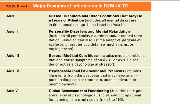 32 841.92] /Contents 141 0 R /group> /Tabs /S /StructParents 7 >> endobj 14 0 obj > /ProcSet [/PDF /Text /ImageB /ImageC /ImageI] >> /MediaBox [0 0 595.32 841.92] /Contents 142 0 R /group> /Tabs /S /StructParents 8 >> endobj 15 0 obj > /ProcSet [/PDF /Text /ImageB /ImageC /ImageI] >> /MediaBox[0 0 595.32 841.92] /Contents 143 0 R /group> /Tabs /S /StructParents 9 >> endobj 16 0 obj > /ProcSet [/PDF /Text /ImageB /ImageC /ImageI] >> /MediaBox [0 0 595.32 841.92] /Contents 145 0 R /group> /Tabs /S /StructParents 10 >> endobj 17 0 obj > /ProcSet [/PDF /Text /ImageB /ImageC /ImageI] >> /MediaBox [0 0 595.32 841.92] /Contents 148 0 R /group> /Tabs /S /StructParents 11 >> endobj 18 0 obj > /ProcSet [/PDF /Text /ImageB /ImageC /ImageI] >> /MediaBox[0 0 595.32 841.92] /Contents 149 0 R /group> /Tabs /S /StructParents 12 >> endobj 19 0 obj > /ProcSet [/PDF /Text /ImageB /ImageC /ImageI] >> /MediaBox [0 0 595.32 841.92] /Contents 150 0 R /group> /Tabs /S /StructParents 13 >> endobj 20 0 obj > /ProcSet [/PDF /Text /ImageB /ImageC /ImageI] >> /MediaBox [0 0 595.
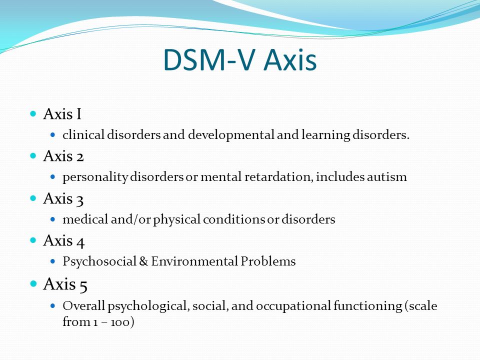 32 841.92] /Contents 151 0 R /group> /Tabs /S /StructParents 14 >> endobj 21 0 obj > /ProcSet [/PDF /Text /ImageB /ImageC /ImageI] >> /MediaBox[0 0 595.32 841.92] /Contents 152 0R /group> /Tabs /S /StructParents 15 >> endobj 22 0 obj > /ProcSet [/PDF /Text /ImageB /ImageC /ImageI] >> /MediaBox [0 0 595.32 841.92] /Contents 153 0R /group> /Tabs /S /StructParents 16 >> endobj 23 0 obj > /ProcSet [/PDF /Text /ImageB /ImageC /ImageI] >> /MediaBox [0 0 595.32 841.92] /Contents 154 0R /group> /Tabs /S /StructParents 17 >> endobj 24 0 obj > /ProcSet [/PDF /Text /ImageB /ImageC /ImageI] >> /MediaBox[0 0 595.32 841.92] /Contents 155 0 R /group> /Tabs /S /StructParents 18 >> endobj 25 0 obj > /ProcSet [/PDF /Text /ImageB /ImageC /ImageI] >> /MediaBox [0 0 595.32 841.92] /Contents 156 0 R /group> /Tabs /S /StructParents 19 >> endobj 26 0 obj > /ProcSet [/PDF /Text /ImageB /ImageC /ImageI] >> /MediaBox [0 0 595.32 841.92] /Contents 157 0 R /group> /Tabs /S /StructParents 20 >> endobj 27 0 obj > /ExtGState> /ProcSet [/PDF /Text /ImageB /ImageC /ImageI] >> /MediaBox[0 0 595.
 32 841.92] /Contents 160 0 R /group> /Tabs /S /StructParents 21 >> endobj 28 0 obj > /ProcSet [/PDF /Text /ImageB /ImageC /ImageI] >> /MediaBox [0 0 595.32 841.92] /Contents 161 0 R /group> /Tabs /S /StructParents 22 >> endobj 29 0 obj > /ProcSet [/PDF /Text /ImageB /ImageC /ImageI] >> /MediaBox [0 0 595.32 841.92] /Contents 162 0 R /group> /Tabs /S /StructParents 23 >> endobj 30 0 obj > /ProcSet [/PDF /Text /ImageB /ImageC /ImageI] >> /MediaBox[0 0 595.32 841.92] /Contents 163 0 R /group> /Tabs /S /StructParents 24 >> endobj 31 0 obj > /ProcSet [/PDF /Text /ImageB /ImageC /ImageI] >> /MediaBox [0 0 595.32 841.92] /Contents 164 0R /group> /Tabs /S /StructParents 25 >> endobj 32 0 obj > /ProcSet [/PDF /Text /ImageB /ImageC /ImageI] >> /MediaBox [0 0 595.32 841.92] /Contents 165 0 R /group> /Tabs /S /StructParents 26 >> endobj 33 0 obj > /ProcSet [/PDF /Text /ImageB /ImageC /ImageI] >> /MediaBox[0 0 595.32 841.92] /Contents 166 0 R /group> /Tabs /S /StructParents 27 >> endobj 34 0 obj > /ProcSet [/PDF /Text /ImageB /ImageC /ImageI] >> /MediaBox [0 0 595.
 32 841.92] /Contents 167 0 R /group> /Tabs /S /StructParents 28 >> endobj 35 0 obj > /ProcSet [/PDF /Text /ImageB /ImageC /ImageI] >> /MediaBox [0 0 595.32 841.92] /Contents 168 0 R /group> /Tabs /S /StructParents 29 >> endobj 36 0 obj > /ProcSet [/PDF /Text /ImageB /ImageC /ImageI] >> /MediaBox[0 0 595.32 841.92] /Contents 169 0 R /group> /Tabs /S /StructParents 30 >> endobj 37 0 obj > /ProcSet [/PDF /Text /ImageB /ImageC /ImageI] >> /MediaBox [0 0 595.32 841.92] /Contents 170 0 R /group> /Tabs /S /StructParents 31 >> endobj 38 0 obj > /ProcSet [/PDF /Text /ImageB /ImageC /ImageI] >> /MediaBox [0 0 595.32 841.92] /Contents 171 0 R /group> /Tabs /S /StructParents 32 >> endobj 39 0 obj > /XObject> /ExtGState> /ProcSet [/PDF /Text /ImageB /ImageC /ImageI] >> /MediaBox[0 0 595.32 841.92] /Contents 173 0 R /group> /Tabs /S /StructParents 33 >> endobj 40 0 obj > /XObject> /ExtGState> /ProcSet [/PDF /Text /ImageB /ImageC /ImageI] >> /MediaBox [0 0 595.32 841.92] /Contents 176 0R /group> /Tabs /S /StructParents 34 >> endobj 41 0 obj > /ProcSet [/PDF /Text /ImageB /ImageC /ImageI] >> /MediaBox [0 0 595.
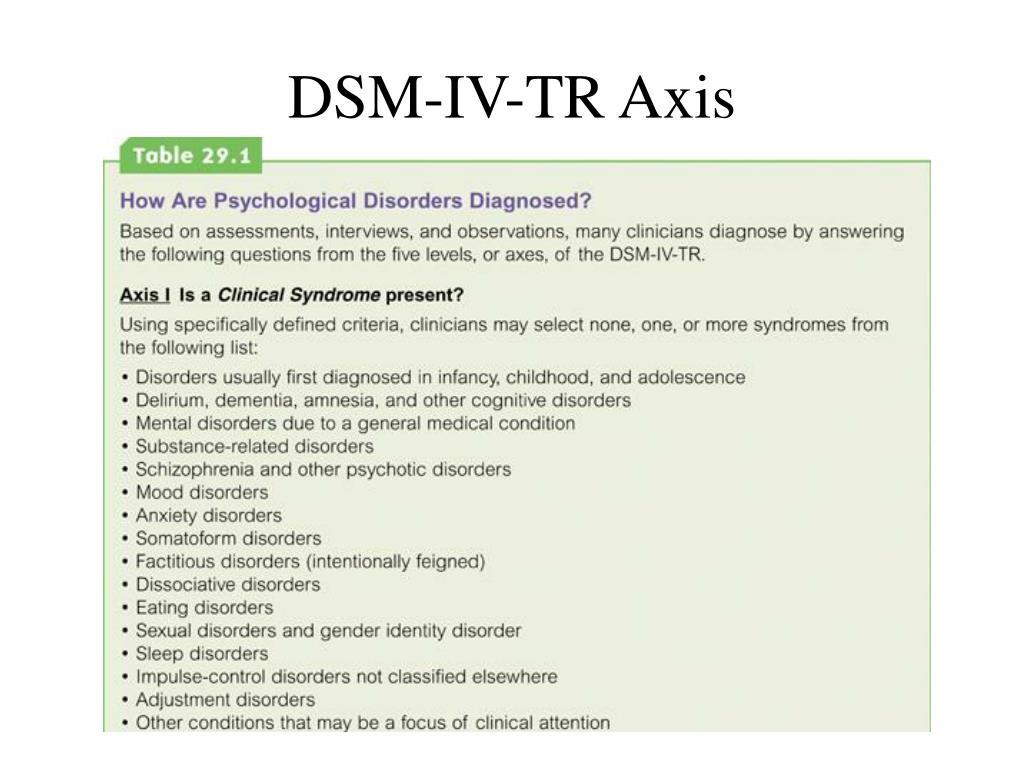 32 841.92] /Contents 177 0R /group> /Tabs /S /StructParents 35 >> endobj 42 0 obj > /ProcSet [/PDF /Text /ImageB /ImageC /ImageI] >> /MediaBox[0 0 595.32 841.92] /Contents 178 0R /group> /Tabs /S /StructParents 36 >> endobj 43 0 obj > /ProcSet [/PDF /Text /ImageB /ImageC /ImageI] >> /MediaBox [0 0 595.32 841.92] /Contents 179 0R /group> /Tabs /S /StructParents 37 >> endobj 44 0 obj > /ProcSet [/PDF /Text /ImageB /ImageC /ImageI] >> /MediaBox [0 0 595.32 841.92] /Contents 180 0 R /group> /Tabs /S /StructParents 38 >> endobj 45 0 obj > /ProcSet [/PDF /Text /ImageB /ImageC /ImageI] >> /MediaBox[0 0 595.32 841.92] /Contents 181 0 R /group> /Tabs /S /StructParents 39 >> endobj 46 0 obj > /ProcSet [/PDF /Text /ImageB /ImageC /ImageI] >> /MediaBox [0 0 595.32 841.92] /Contents 182 0 R /group> /Tabs /S /StructParents 40 >> endobj 47 0 obj > /ProcSet [/PDF /Text /ImageB /ImageC /ImageI] >> /MediaBox [0 0 595.32 841.92] /Contents 183 0 R /group> /Tabs /S /StructParents 41 >> endobj 48 0 obj > /ProcSet [/PDF /Text /ImageB /ImageC /ImageI] >> /MediaBox[0 0 595.
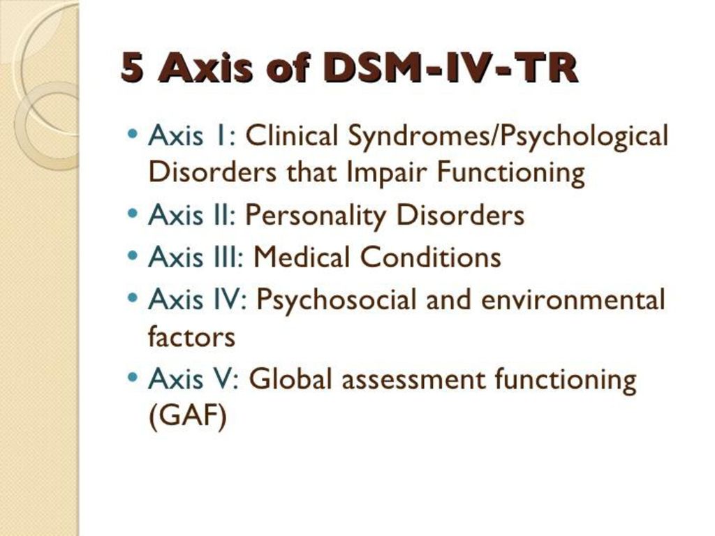 32 841.92] /Contents 184 0 R /group> /Tabs /S /StructParents 42 >> endobj 49 0 obj > /ProcSet [/PDF /Text /ImageB /ImageC /ImageI] >> /MediaBox [0 0 595.32 841.92] /Contents 185 0R /group> /Tabs /S /StructParents 43 >> endobj 50 0 obj > /ProcSet [/PDF /Text /ImageB /ImageC /ImageI] >> /MediaBox [0 0 595.32 841.92] /Contents 186 0R /group> /Tabs /S /StructParents 44 >> endobj 51 0 obj > /ProcSet [/PDF /Text /ImageB /ImageC /ImageI] >> /MediaBox[0 0 595.32 841.92] /Contents 187 0R /group> /Tabs /S /StructParents 45 >> endobj 52 0 obj > /ProcSet [/PDF /Text /ImageB /ImageC /ImageI] >> /MediaBox [0 0 595.32 841.92] /Contents 188 0 R /group> /Tabs /S /StructParents 46 >> endobj 53 0 obj > /ProcSet [/PDF /Text /ImageB /ImageC /ImageI] >> /MediaBox [0 0 595.32 841.92] /Contents 189 0 R /group> /Tabs /S /StructParents 47 >> endobj 54 0 obj > /ProcSet [/PDF /Text /ImageB /ImageC /ImageI] >> /MediaBox[0 0 595.32 841.92] /Contents 190 0R /group> /Tabs /S /StructParents 48 >> endobj 55 0 obj > /ProcSet [/PDF /Text /ImageB /ImageC /ImageI] >> /MediaBox [0 0 595.
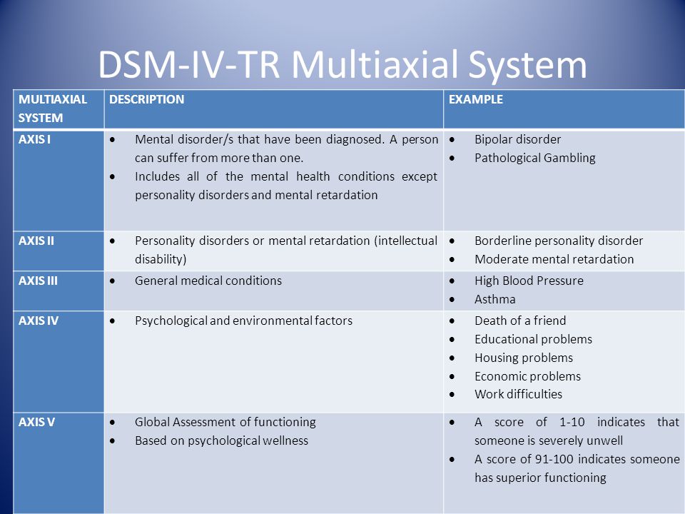 32 841.92] /Contents 191 0 R /group> /Tabs /S /StructParents 49 >> endobj 56 0 obj > /ProcSet [/PDF /Text /ImageB /ImageC /ImageI] >> /MediaBox [0 0 595.32 841.92] /Contents 192 0R /group> /Tabs /S /StructParents 50 >> endobj 57 0 obj > /ProcSet [/PDF /Text /ImageB /ImageC /ImageI] >> /MediaBox[0 0 595.32 841.92] /Contents 193 0 R /group> /Tabs /S /StructParents 51 >> endobj 58 0 obj > /ProcSet [/PDF /Text /ImageB /ImageC /ImageI] >> /MediaBox [0 0 595.32 841.92] /Contents 194 0 R /group> /Tabs /S /StructParents 52 >> endobj 59 0 obj > /ProcSet [/PDF /Text /ImageB /ImageC /ImageI] >> /MediaBox [0 0 595.32 841.92] /Contents 195 0 R /group> /Tabs /S /StructParents 53 >> endobj 60 0 obj > /ProcSet [/PDF /Text /ImageB /ImageC /ImageI] >> /MediaBox[0 0 595.32 841.92] /Contents 196 0R /group> /Tabs /S /StructParents 54 >> endobj 61 0 obj > /ProcSet [/PDF /Text /ImageB /ImageC /ImageI] >> /MediaBox [0 0 595.32 841.92] /Contents 197 0R /group> /Tabs /S /StructParents 55 >> endobj 62 0 obj > /ProcSet [/PDF /Text /ImageB /ImageC /ImageI] >> /MediaBox [0 0 595.
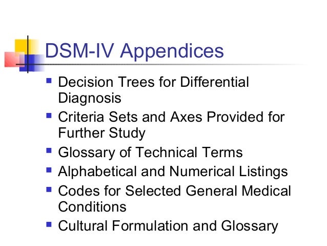 32 841.92] /Contents 198 0R /group> /Tabs /S /StructParents 56 >> endobj 63 0 obj > /ProcSet [/PDF /Text /ImageB /ImageC /ImageI] >> /MediaBox[0 0 595.32 841.92] /Contents 199 0 R /group> /Tabs /S /StructParents 57 >> endobj 64 0 obj > /ProcSet [/PDF /Text /ImageB /ImageC /ImageI] >> /MediaBox [0 0 595.32 841.92] /Contents 200 0 R /group> /Tabs /S /StructParents 58 >> endobj 65 0 obj > /ProcSet [/PDF /Text /ImageB /ImageC /ImageI] >> /MediaBox [0 0 595.32 841.92] /Contents 201 0 R /group> /Tabs /S /StructParents 59 >> endobj 66 0 obj > /ProcSet [/PDF /Text /ImageB /ImageC /ImageI] >> /MediaBox[0 0 595.32 841.92] /Contents 202 0 R /group> /Tabs /S /StructParents 60 >> endobj 67 0 obj > /ProcSet [/PDF /Text /ImageB /ImageC /ImageI] >> /MediaBox [0 0 595.32 841.92] /Contents 203 0 R /group> /Tabs /S /StructParents 61 >> endobj 68 0 obj > /ProcSet [/PDF /Text /ImageB /ImageC /ImageI] >> /MediaBox [0 0 595.32 841.92] /Contents 204 0 R /group> /Tabs /S /StructParents 62 >> endobj 69 0 obj > /ProcSet [/PDF /Text /ImageB /ImageC /ImageI] >> /MediaBox[0 0 595.
 32 841.92] /Contents 205 0 R /group> /Tabs /S /StructParents 63 >> endobj 70 0 obj > /ProcSet [/PDF /Text /ImageB /ImageC /ImageI] >> /MediaBox [0 0 595.32 841.92] /Contents 206 0 R /group> /Tabs /S /StructParents 64 >> endobj 71 0 obj > /ProcSet [/PDF /Text /ImageB /ImageC /ImageI] >> /MediaBox [0 0 595.32 841.92] /Contents 207 0 R /group> /Tabs /S /StructParents 65 >> endobj 72 0 obj > /ProcSet [/PDF /Text /ImageB /ImageC /ImageI] >> /MediaBox[0 0 595.32 841.92] /Contents 208 0 R /group> /Tabs /S /StructParents 66 >> endobj 73 0 obj > /ProcSet [/PDF /Text /ImageB /ImageC /ImageI] >> /MediaBox [0 0 595.32 841.92] /Contents 209 0 R /group> /Tabs /S /StructParents 67 >> endobj 74 0 obj > /ProcSet [/PDF /Text /ImageB /ImageC /ImageI] >> /MediaBox [0 0 595.32 841.92] /Contents 210 0 R /group> /Tabs /S /StructParents 68 >> endobj 75 0 obj > /ProcSet [/PDF /Text /ImageB /ImageC /ImageI] >> /MediaBox[0 0 595.32 841.92] /Contents 211 0 R /group> /Tabs /S /StructParents 69 >> endobj 76 0 obj > /ProcSet [/PDF /Text /ImageB /ImageC /ImageI] >> /MediaBox [0 0 595.
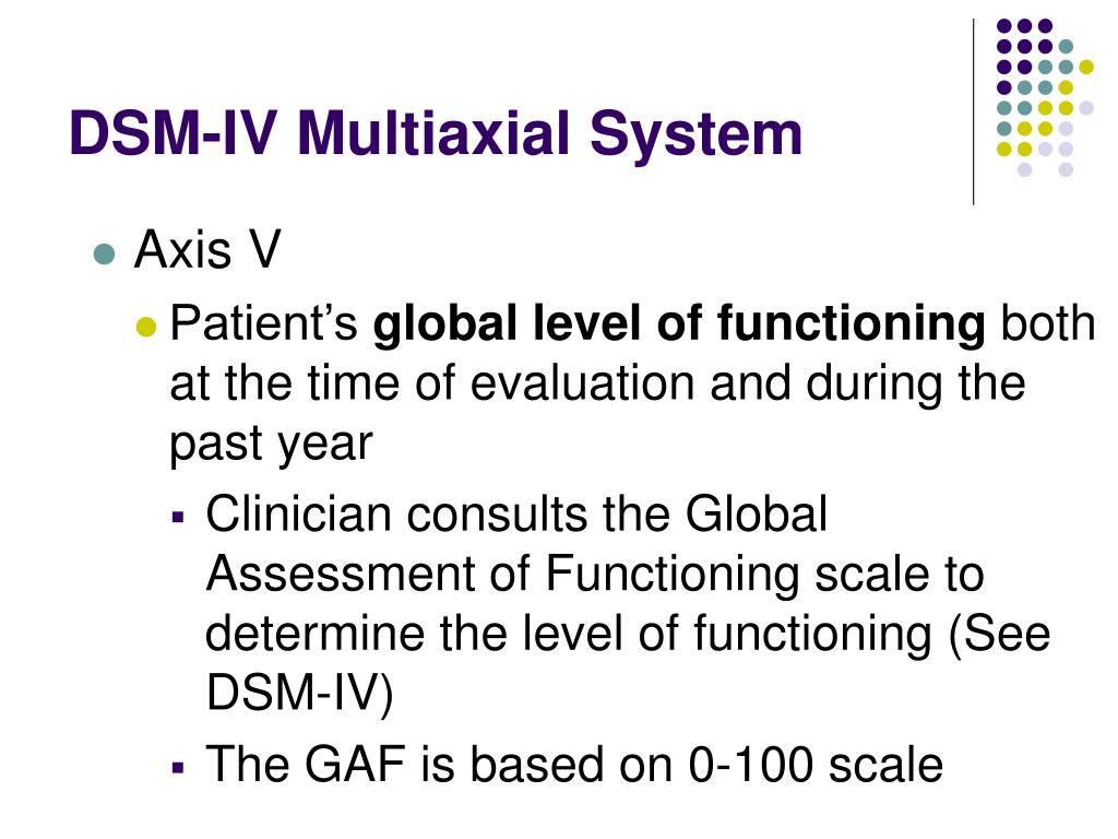 32 841.92] /Contents 212 0 R /group> /Tabs /S /StructParents 70 >> endobj 77 0 obj > /ProcSet [/PDF /Text /ImageB /ImageC /ImageI] >> /MediaBox [0 0 595.32 841.92] /Contents 213 0 R /group> /Tabs /S /StructParents 71 >> endobj 78 0 obj > /ProcSet [/PDF /Text /ImageB /ImageC /ImageI] >> /MediaBox[0 0 595.32 841.92] /Contents 214 0 R /group> /Tabs /S /StructParents 72 >> endobj 79 0 obj > /ProcSet [/PDF /Text /ImageB /ImageC /ImageI] >> /MediaBox [0 0 595.32 841.92] /Contents 215 0 R /group> /Tabs /S /StructParents 73 >> endobj 80 0 obj > /ProcSet [/PDF /Text /ImageB /ImageC /ImageI] >> /MediaBox [0 0 595.32 841.92] /Contents 216 0 R /group> /Tabs /S /StructParents 74 >> endobj 81 0 obj > /ProcSet [/PDF /Text /ImageB /ImageC /ImageI] >> /MediaBox[0 0 595.32 841.92] /Contents 217 0 R /group> /Tabs /S /StructParents 75 >> endobj 82 0 obj > /ProcSet [/PDF /Text /ImageB /ImageC /ImageI] >> /MediaBox [0 0 595.32 841.92] /Contents 218 0R /group> /Tabs /S /StructParents 76 >> endobj 83 0 obj > /ProcSet [/PDF /Text /ImageB /ImageC /ImageI] >> /MediaBox [0 0 595.
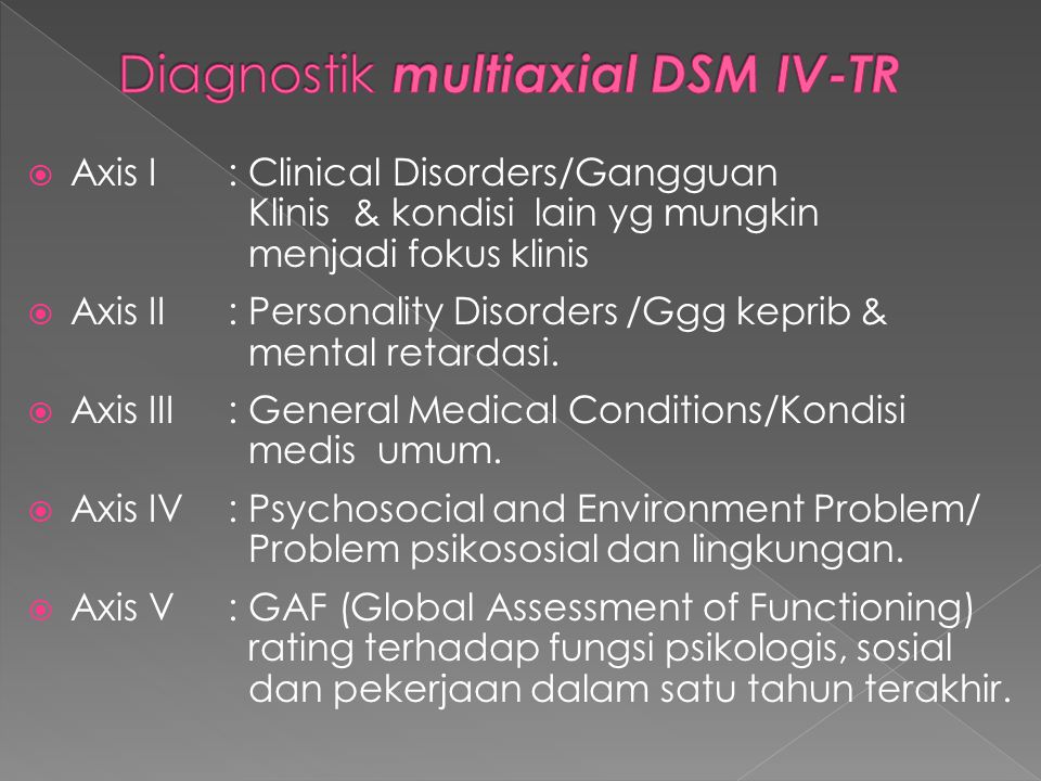 32 841.92] /Contents 219 0 R /group> /Tabs /S /StructParents 77 >> endobj 84 0 obj > /ProcSet [/PDF /Text /ImageB /ImageC /ImageI] >> /MediaBox[0 0 595.32 841.92] /Contents 220 0R /group> /Tabs /S /StructParents 78 >> endobj 85 0 obj > /ProcSet [/PDF /Text /ImageB /ImageC /ImageI] >> /MediaBox [0 0 595.32 841.92] /Contents 221 0 R /group> /Tabs /S /StructParents 79 >> endobj 86 0 obj > /ExtGState> /ProcSet [/PDF /Text /ImageB /ImageC /ImageI] >> /MediaBox [0 0 595.32 841.92] /Contents 222 0 R /group> /Tabs /S /StructParents 80 >> endobj 87 0 obj > /ExtGState> /ProcSet [/PDF /Text /ImageB /ImageC /ImageI] >> /MediaBox[0 0 595.32 841.92] /Contents 223 0 R /group> /Tabs /S /StructParents 81 >> endobj 88 0 obj > /ExtGState> /ProcSet [/PDF /Text /ImageB /ImageC /ImageI] >> /MediaBox [0 0 595.32 841.92] /Contents 224 0R /group> /Tabs /S /StructParents 82 >> endobj 89 0 obj > /ExtGState> /ProcSet [/PDF /Text /ImageB /ImageC /ImageI] >> /MediaBox [0 0 595.32 841.92] /Contents 225 0 R /group> /Tabs /S /StructParents 83 >> endobj 90 0 obj > /ExtGState> /ProcSet [/PDF /Text /ImageB /ImageC /ImageI] >> /MediaBox[0 0 595.
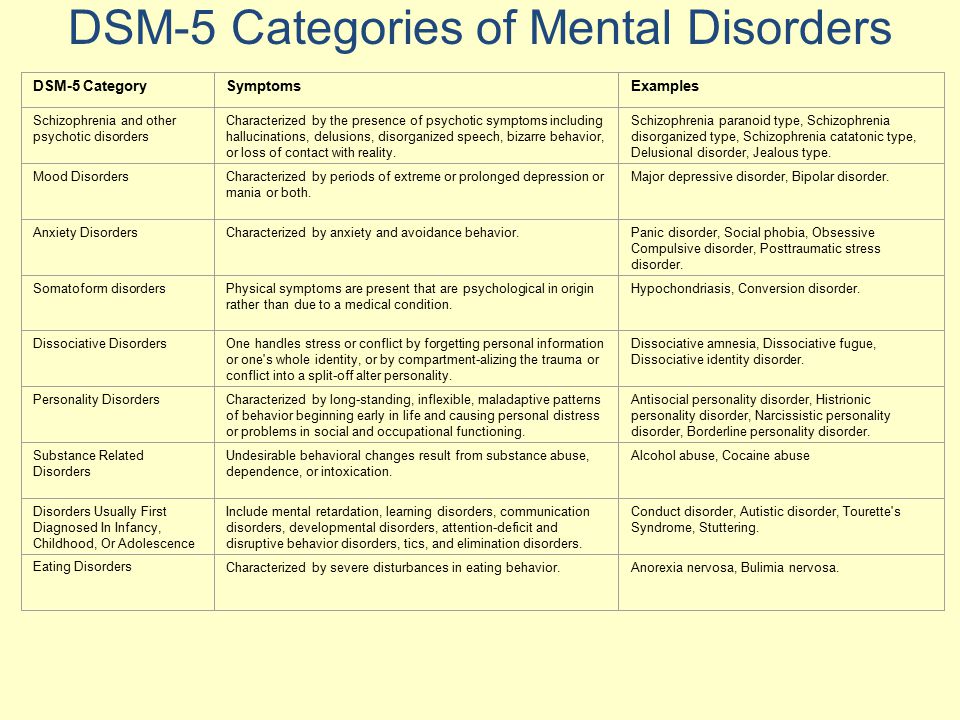 32 841.92] /Contents 226 0R /group> /Tabs /S /StructParents 84 >> endobj 91 0 obj > /ExtGState> /ProcSet [/PDF /Text /ImageB /ImageC /ImageI] >> /MediaBox [0 0 595.32 841.92] /Contents 227 0R /group> /Tabs /S /StructParents 85 >> endobj 92 0 obj > /ExtGState> /ProcSet [/PDF /Text /ImageB /ImageC /ImageI] >> /MediaBox [0 0 595.32 841.92] /Contents 228 0 R /group> /Tabs /S /StructParents 86 >> endobj 93 0 obj > /ExtGState> /ProcSet [/PDF /Text /ImageB /ImageC /ImageI] >> /MediaBox[0 0 595.32 841.92] /Contents 229 0 R /group> /Tabs /S /StructParents 87 >> endobj 94 0 obj > /ExtGState> /ProcSet [/PDF /Text /ImageB /ImageC /ImageI] >> /MediaBox [0 0 595.32 841.92] /Contents 230 0 R /group> /Tabs /S /StructParents 88 >> endobj 95 0 obj > /ExtGState> /ProcSet [/PDF /Text /ImageB /ImageC /ImageI] >> /MediaBox [0 0 595.32 841.92] /Contents 231 0 R /group> /Tabs /S /StructParents 89 >> endobj 96 0 obj > /ExtGState> /ProcSet [/PDF /Text /ImageB /ImageC /ImageI] >> /MediaBox[0 0 595.32 841.92] /Contents 232 0 R /group> /Tabs /S /StructParents 90 >> endobj 97 0 obj > /ExtGState> /ProcSet [/PDF /Text /ImageB /ImageC /ImageI] >> /MediaBox [0 0 595.
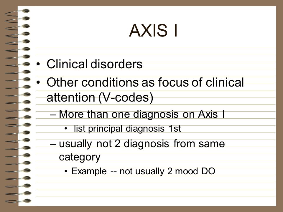 32 841.92] /Contents 234 0 R /group> /Tabs /S /StructParents 91 >> endobj 98 0 obj > /ExtGState> /ProcSet [/PDF /Text /ImageB /ImageC /ImageI] >> /MediaBox [0 0 595.32 841.92] /Contents 235 0 R /group> /Tabs /S /StructParents 92 >> endobj 99 0 obj > /ExtGState> /ProcSet [/PDF /Text /ImageB /ImageC /ImageI] >> /MediaBox[0 0 595.32 841.92] /Contents 237 0R /group> /Tabs /S /StructParents 93 >> endobj 100 0 obj > /ExtGState> /ProcSet [/PDF /Text /ImageB /ImageC /ImageI] >> /MediaBox [0 0 595.32 841.92] /Contents 238 0 R /group> /Tabs /S /StructParents 94 >> endobj 101 0 obj > /ExtGState> /ProcSet [/PDF /Text /ImageB /ImageC /ImageI] >> /MediaBox [0 0 595.32 841.92] /Contents 239 0 R /group> /Tabs /S /StructParents 95 >> endobj 102 0 obj > /ExtGState> /ProcSet [/PDF /Text /ImageB /ImageC /ImageI] >> /MediaBox[0 0 595.32 841.92] /Contents 240 0 R /group> /Tabs /S /StructParents 96 >> endobj 103 0 obj > /ExtGState> /ProcSet [/PDF /Text /ImageB /ImageC /ImageI] >> /MediaBox [0 0 595.32 841.92] /Contents 241 0 R /group> /Tabs /S /StructParents 97 >> endobj 104 0 obj > /ExtGState> /ProcSet [/PDF /Text /ImageB /ImageC /ImageI] >> /MediaBox [0 0 595.
 32 841.92] /Contents 242 0 R /group> /Tabs /S /StructParents 98 >> endobj 105 0 obj > /ExtGState> /ProcSet [/PDF /Text /ImageB /ImageC /ImageI] >> /MediaBox[0 0 595.32 841.92] /Contents 243 0 R /group> /Tabs /S /StructParents 99 >> endobj 106 0 obj > /ExtGState> /ProcSet [/PDF /Text /ImageB /ImageC /ImageI] >> /MediaBox [0 0 595.32 841.92] /Contents 244 0R /group> /Tabs /S /StructParents 100 >> endobj 107 0 obj > /ExtGState> /ProcSet [/PDF /Text /ImageB /ImageC /ImageI] >> /MediaBox [0 0 595.32 841.92] /Contents 245 0R /group> /Tabs /S /StructParents 101 >> endobj 108 0 obj > /ExtGState> /ProcSet [/PDF /Text /ImageB /ImageC /ImageI] >> /MediaBox[0 0 595.32 841.92] /Contents 246 0R /group> /Tabs /S /StructParents 102 >> endobj 109 0 obj > /ExtGState> /ProcSet [/PDF /Text /ImageB /ImageC /ImageI] >> /MediaBox [0 0 595.32 841.92] /Contents 247 0R /group> /Tabs /S /StructParents 103 >> endobj 110 0 obj > /ExtGState> /ProcSet [/PDF /Text /ImageB /ImageC /ImageI] >> /MediaBox [0 0 595.32 841.