Different types of projection
Projection types—ArcMap | Documentation
- Projection types illustrated
Because maps are flat, some of the simplest projections are made onto geometric shapes that can be flattened without stretching their surfaces. These are called developable surfaces. Some common examples are cones, cylinders, and planes. A map projection systematically projects locations from the surface of a spheroid to representative positions on a flat surface using mathematical algorithms.
The first step in projecting from one surface to another is creating one or more points of contact. Each contact is called a point (or line) of tangency. A planar projection is tangential to the globe at one point. Tangential cones and cylinders touch the globe along a line. If the projection surface intersects the globe instead of merely touching its surface, the resulting projection is a secant rather than a tangent case. Whether the contact is tangent or secant, the contact points or lines are significant because they define locations of zero distortion.
Lines of true scale include the central meridian and standard parallels and are sometimes called standard lines. In general, distortion increases with the distance from the point of contact.
Many common map projections are classified according to the projection surface used: conic, cylindrical, or planar.
- Learn more about the conic projection.
- Learn more about the cylindrical projection.
- Learn more about the planar projection.
Projection types illustrated
Each of the main projection types—conic, cylindrical, and planar—are illustrated below.
Conic (tangent)
A cone is placed over a globe. The cone and globe meet along a latitude line. This is the standard parallel. The cone is cut along the line of longitude that is opposite the central meridian and flattened into a plane.Conic (secant)
A cone is placed over a globe but cuts through the surface. The cone and globe meet along two latitude lines. These are the standard parallels. The cone is cut along the line of longitude that is opposite the central meridian and flattened into a plane.
Cylindrical aspects
A cylinder is placed over a globe. The cylinder can touch the globe along a line of latitude (normal case), a line of longitude (transverse case), or another line (oblique case).Planar aspects
A plane is placed over a globe. The plane can touch the globe at the pole (polar case), the equator (equatorial case), or another line (oblique case).Polar aspect (different perspectives)
Azimuthal, or planar projections can have different perspective points. The gnomonic projection's point is at the center of the globe. The opposite side of the globe from the point of contact is used for a stereographic projection. The perspective point for an orthographic projection is at infinity.Related topics
Projection Methods Used in Mechanical Drawing
Engineering drawings are a highly detailed way of representing three-dimensional objects on a two-dimensional surface, such as paper or a computer screen.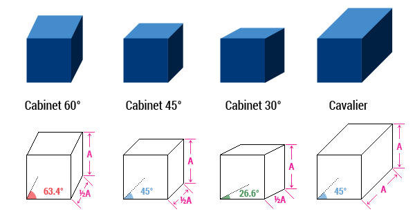 This can be accomplished by including multiple views of different sides of an object in a single image or by including all three dimensions of an object in a single image. Construction drawings are the result of the use of engineering drawings to represent objects.
Every engineer must be able to read and interpret drawings and the data contained within them. Projection methods are used to represent a 3D object in simple terms so that it can be understood more easily. It’s used in mechanical drawing and design so that the structure created by a designer can be communicated to manufacturers and builders. A pictorial view of a design can’t always show the details in complicated shapes that contain information related to how it will be manufactured.
The spatial relationship between 3-D projections and Multiview projections must be understood.
Let’s take a look at the projection system and the different types of projection used in engineering drawings.
What is a projection in a mechanical engineering drawing?
The purpose of engineering drawings, whether freehand sketching or computer-aided design (CAD), is to represent a physical object or a visual representation of an object so that it can be communicated to others.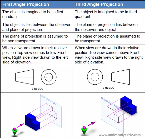
In an engineering drawing, a projection is a geometrically represented image (visual image or figure) of an object obtained on a surface or plane. The object could be a point, line, plane, solid, machine component, or building.
Projections in technical drawings are created based on the observer or reader of the technical drawing. The observer is usually looking at the projection plane, also known as technical drawing paper. Furthermore, the projectors generate a projected view of the 3D model on technical drawing paper. Projectors are also rays that originate from the observer’s eyes or the observer himself. A view of the part can be generated on the projection plane between the observer and the part.
Visualize your Dream DesignConnect with 3D CAD Expert
Types of Projection Methods Used in Mechanical Drawing
There are four main types of projection methods used in mechanical drawing in order to convey information such as geometry, dimensions, tolerances, material, and finish.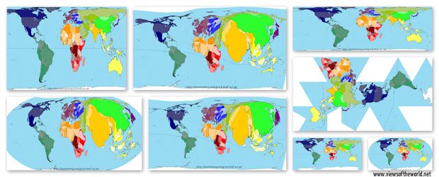 Let’s take a look at how they are drawn.
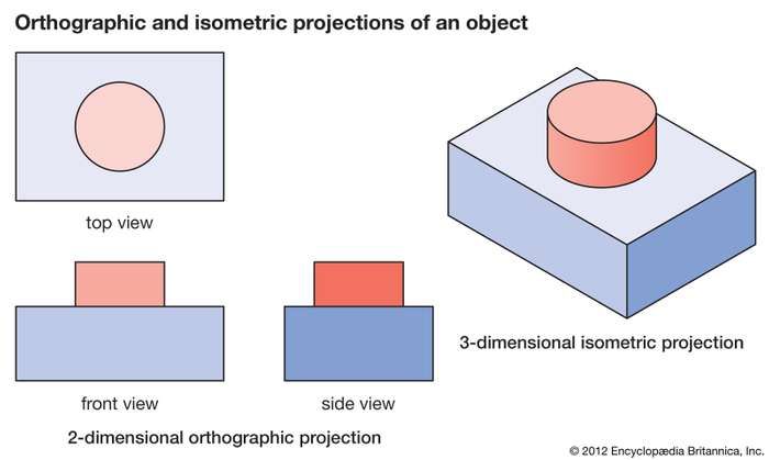
The orthographic projection shows a 3D object in two dimensions so that you can see three views: the front view, the side view, and the top view. It is usually positioned relative to the rules of first-angle or third-angle projection. The difference between the two is the view. However, it is not a realistic view of the object, because it requires multiple views to get all of the information in order to “see” the design. But more accurate measurements can be obtained because all views have the same scale.
An orthographic projection can also include a section view, which is when a portion of the object is cross-sectioned along the specified plane, and the information about that section is displayed. It’s used to show internal specifications.
2.
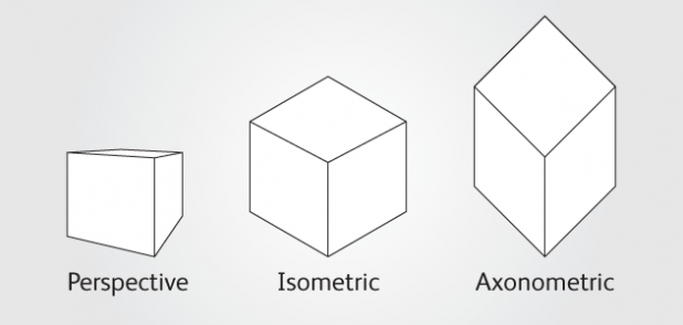
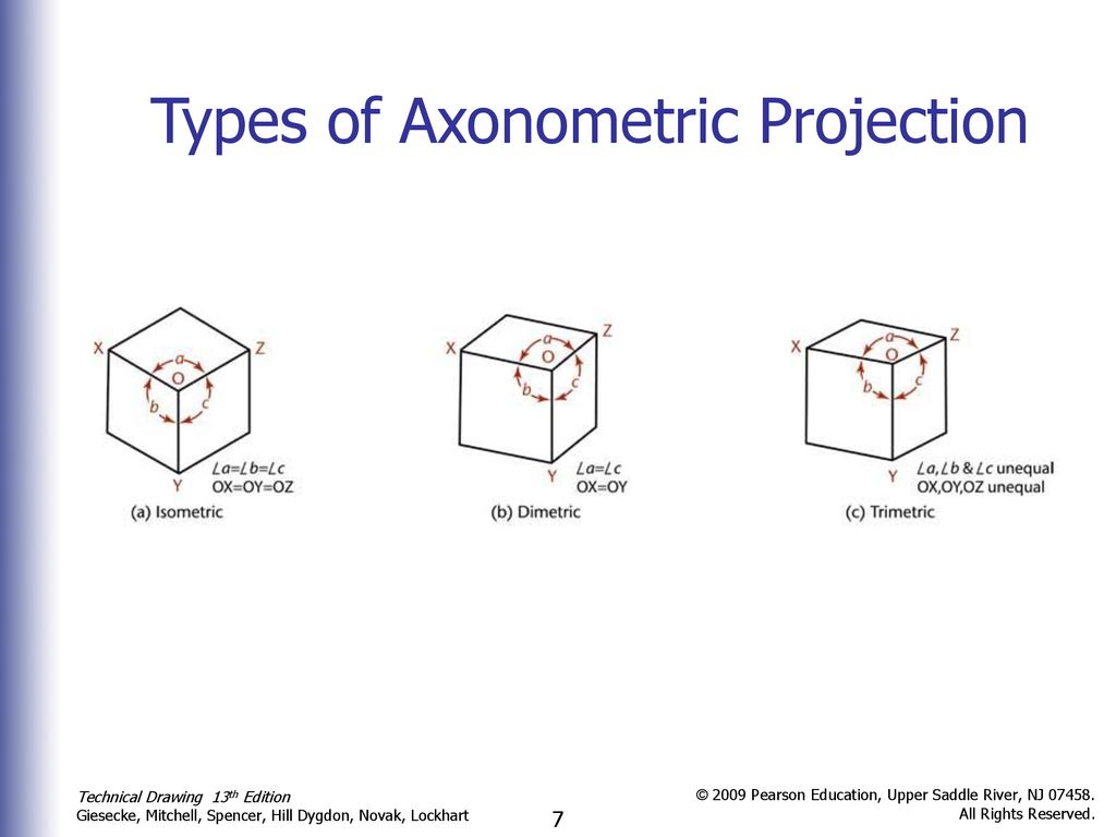
Axonometric ProjectionAxonometric is another type of orthographic projection. It is considered complex because only one image is drawn on the paper’s plane.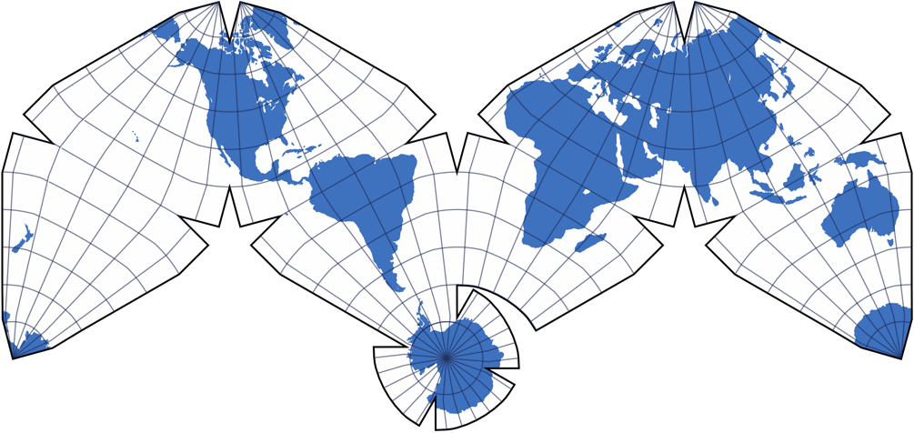 There are three types of classifications. The most common is isometric, where the angles between the three axes are equal. The second is diametric. Only two of the angles between the axes are equal in this type. Trimetric is the third type. It can have three axes with different angles between them. It is the most common type. Axonometric projection is good for rectangular or square objects rather than objects with curved lines.
3.
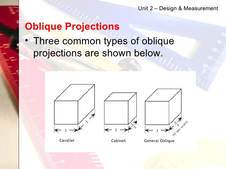
Oblique ProjectionOblique is a simple type of projection that only requires one image. It can be drawn with traditional tools because it’s not complex. It depicts a 2D image of a 3D object. The object is drawn from the front view, and then the other areas are added in relation to it. It can be divided into two types based on the scaling of the object: cavalier projection, which uses a 1:1 scale, and cabinet projection, which uses a 2:1 scale. It uses parallel lines to produce the source of the object in the image.
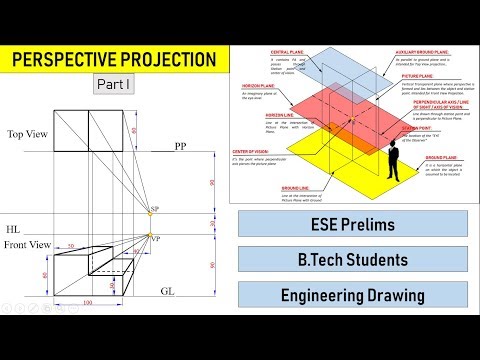
4. Perspective Projection
Of the four methods, perspective projection is not based on parallel lines. It is an approximate representation of the object as it would be seen by the eye with respect to depth perception. The projection lines emerge from a single point, showing the closer part larger than the more distant part. The object can feel more realistic with this projection, but it does require a good imagination.
Outsource CAD Drafting Projects – Save on Time, Effort and Money
Get the most for your money by working with one of the top CAD outsourcing firms in the world. If you’re interested in lowering costs within your business, give Indovance a call. We can help you decrease your project time, giving you an advantage over your competitors. We offer AutoCAD, BIM modeling services, engineering, architecture services, and more. Call us today to learn more about all of the outsourcing services we offer so that your business can grow to new levels.
Follow Indovance Inc for AEC Industry Updates and Global Construction News.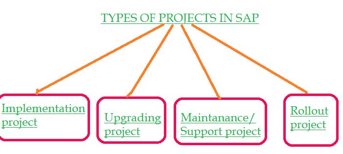
About Indovance
Indovance Inc with its exclusive delivery hub in India is a global CAD technology partner serving the needs of the AEC industry since 2003. We focus on the unique need of each project or client and believe in addressing the real challenges and guarantee that the process will be well-coordinated, smooth, efficient, and hassle-free.
We collaborate with our customers around the world to develop bespoke business solutions using our enormous engineering talent pool and state-of-the-art technology. To deliver long-term engineering and business strategies, we align with your culture and processes to create an unbreakable partnership. With over 500 full-time employees and more than 600 customers in the US, Europe, India, and Asia, we are poised for the next level of success.
Indovance acts as a catalyst, Empowering You for positive change and supporting you to Do More.
For more queries regarding any of the above-mentioned topics, feel free to connect with us on our website www.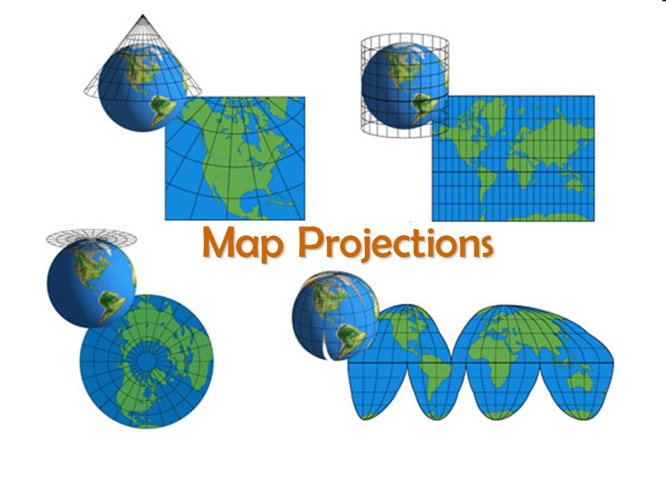 indovance.com or contact us on +1-919-238-4044
Visualize QUALITY & SUSTAINABILITY
Connect with a Specialized CAD Partner
Projection types—ArcMap | Documentation
- Project types: illustrations
Since maps are flat, some of the simplest projections use geometric shapes that can be unfolded onto a plane without stretching or tearing their surfaces. They are called developable surfaces. Typical examples are cones, cylinders and planes. The map projection systematically projects sections of the spheroid surface to the corresponding positions of the plane using mathematical algorithms
The first step in projecting one surface onto another is to create one or more contact points. Each such point is called a touch point. As will be shown below in the Azimuth Projections section, the Azimuthal projection is tangential to the earth's surface at only one point. Cones and cylinders touch the globe along a line.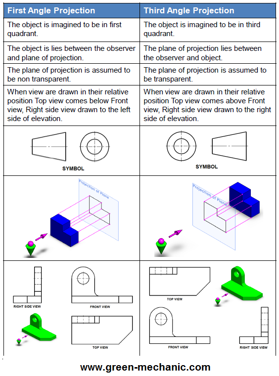 If the projection surface intersects the globe rather than touching its surface, then the resulting projection is secant, not tangent. Whether the contact is tangent or secant, its location is significant, as it defines the point or lines of zero distortion. This true scale line is often referred to as the standard line. In general, projection distortion increases with increasing distance from the point of contact.
Many common map projections can be classified according to the projection surface they use: conical, cylindrical, or azimuth (projected onto a plane).
- Learn more about conic projection.
- Learn more about cylindrical projection.
- Learn more about azimuthal projection.
Project types: illustrations
This page shows the main types of projections - Conic, Cylindrical and Azimuth.
Conical (tangential)
The cone is placed on the globe. The cone and the globe touch each other along the line of latitude.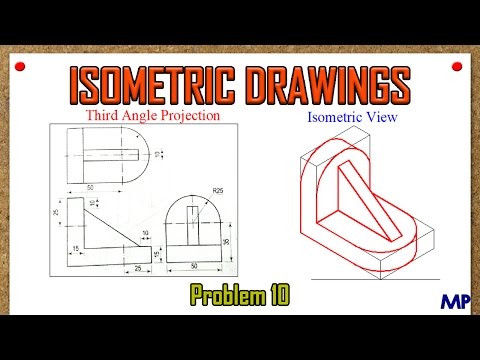 It is called the standard parallel. The cone is "cut" along the line of longitude opposite to the central meridian and unfolds onto a plane.
 Conical (secant)
The cone also wraps around the globe, but passes through the surface. Therefore, the cone and the globe have two lines of latitude in common. These are lines of standard parallels. The cone is "cut" along the line of longitude opposite to the central meridian and unfolds onto a plane.Cylindrical - variations
A cylinder wraps around the globe. A cylinder can touch the globe along a line of latitude (normal projection), a line of longitude (transverse), or some other line (oblique).Azimuthal - varieties
The map sheet is located on the globe. The sheet can touch the globe at a pole point (polar projection), at the equator (equatorial), or at any other point (oblique).Polar - variations (different perspectives)
Azimuthal projection can be built from different perspective points. Gnomonic - the point of perspective is located in the center of the globe.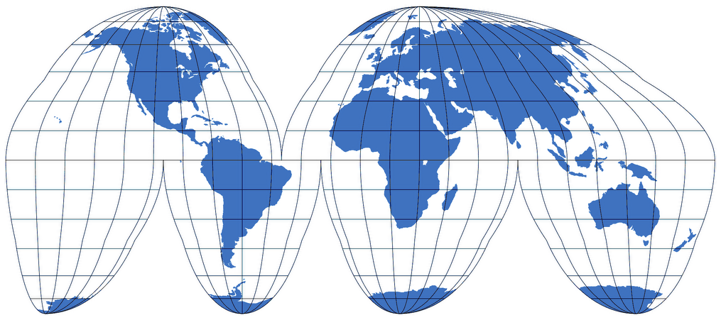 Stereographic - the perspective point is located on the back side of the globe. Orthographic - the point is at an infinite distance from the globe.
 Related Sections
Projection
Projection
Projection
depict the real world in a flat or planar coordinate system. When creating maps the ellipsoid of revolution must be turned onto the plane. It is clear that he cannot be unfolded on a plane without folds or breaks, therefore, when creating maps, they resort to the help of map projections, in which the display of the surface of the earth or other celestial body occurs according to strict mathematical laws. These laws express functional connection of the coordinates of points on the surface of the ellipsoid of revolution and the plane (map). Such a display is based on a system of geographical or geodetic coordinates, whose coordinate lines are meridians and parallels.
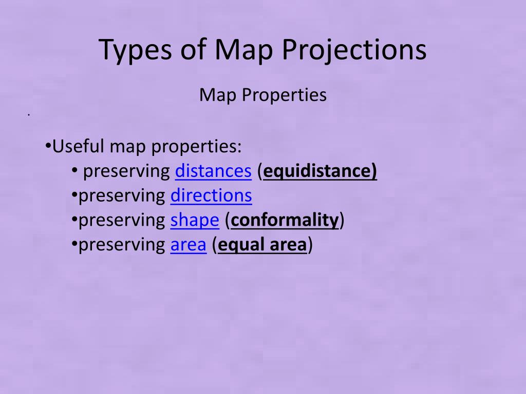
Different projections have different types of distortion. Some projections are designed with minimizing the distortion of one or two characteristics of the data. Projection can save area objects, but change their shape. Stretching and shrinking individual parts of the image mapped surface in one projection or another is inevitably accompanied by distortions lengths, areas and angles. In some projections, you can avoid distortion of angles, in others - areas, but the lengths of the lines will be distorted in all projections, except for individual points or some lines on the map, which we will talk about a little later.
Map projections are designed for specific purposes, as some map projections can be used to display large-scale features on limited area, others - for compiling small-scale maps of the world.
Projections are classified according to the following main features:
-
by the nature of the distortions;
-
in the form of a normal grid of parallels and meridians;
-
for the orientation of the secondary surface.
According to the nature of distortions projections are distinguished:
-
Equal area - no distortion areas. Significant distortion of angles and shapes. These projections are often used for land management purposes, area measurements and population density mapping, as well as for research in one specific area.
-
Equangular - no corner distortion, as a result, the shapes of the figures are not distorted in them, and the scale of lengths at any point remains the same in all directions. In these projections, maps of large areas are characterized by a significant distortion of areas. Very handy for navigating tasks. The angle on the ground is always equal to the angle on the map, the line is straight on the ground, straight on the map.
 The main example of this projection is the transverse cylindrical projection. Mercator (1569d) and it is still used for maritime navigation kart.
 -
Arbitrary - they have distortion and corners, and areas, but to a much lesser extent than in equal-area and equiangular projections, so they are the most used.
Among them, a special place is occupied by equidistant projections, in which the scale lengths in one of the main directions is kept constant.
According to according to the type of normal grid of parallels and meridians distinguish between projections:
-
Conic are projections in which the surface ellipsoid is transferred to the lateral surface of the tangent to it (a) or secant to it cone (b), and then the latter is cut along the line forming it and deployed into plane.
 In conic projections, parallels are arcs of one-centered circles, and meridians - straight lines converging at one point (pole) at angles, proportional to the difference in longitudes (c). In such projections, distortions do not depend on longitude. Particularly suitable for areas stretched along parallels. All maps territories of the USSR are often compiled in equiangular and equidistant conic projections.
 Figure 30. Conic projection
-
Cylindrical are projections in which the earth's surface is projected onto the side surface of the cylinder, which then unfolds into a plane. The cylinder can be tangent to the globe or cutting it. In the first case, lengths are stored along the equator. In the second, two standard parallels.
Cylindrical projections are straight, oblique and transverse.
 In straight cylindrical projections, the same parts of the surface are depicted in the same way along the cut line in the eastern and western parts of the map, which makes it easy to read the map latitude zones. Oblique cylindrical projections have a geographic grid that gives an idea of the sphericity of the globe. As the latitude of the pole decreases, the curvature parallels increases, and their length decreases, which gives an idea of sphericity of the earth.
 Cylindrical projections are used to map small and large scales - from general geographical to special. For example, air navigation route flight charts are most often compiled in oblique and transverse cylindrical conformal projections (on the ball).
Figure 31 Cylindrical projection
-
Azimuthal - projections in which the parallels normal grid are concentric circles, and meridians are their radii, diverging from a common center of parallels at angles equal to the difference in longitudes.
 Each a point on the map has the same azimuth with respect to the mean meridian, which the same point has with the mean meridian on the sphere. Name of azimuthal projections obtained due to their main property to preserve the azimuths of the lines without distortion, emerging from the point of contact of the picture plane.
 Figure 32. Azimuth projection
Direct, oblique, and transverse azimuth projections are used, as determined by the latitude of the central point of the projection, the choice of which depends on the location of the territory. Meridians and parallels in oblique and transverse projections are depicted by curved lines, beyond except for the middle meridian, which is the central point of the projection. IN transverse projections of the straight line also depict the equator: it is the second axis symmetry.
-
Pseudo-conic - projections with parallels represented by arcs of concentric circles, one of the meridians, called the middle one is a straight line, and the rest are curves symmetrical about the middle one. An example of a pseudoconic projection is the equal area pseudoconic Bonn projection.
-
Pseudo-cylindrical - projections in which all parallels are shown as parallel lines, the middle meridian as a straight line, perpendicular to the parallels, and the other meridians are curved. And the middle meridian is the axis of symmetry of the projection. Pseudocylindrical projections are mainly used to depict the entire earth's surface or significant parts of it on a small scale. Therefore, the earth's surface is taken as the surface of a ball with radius R.